2. In case of models with electrical control circuit
・In case of the lubrication models with electrical control
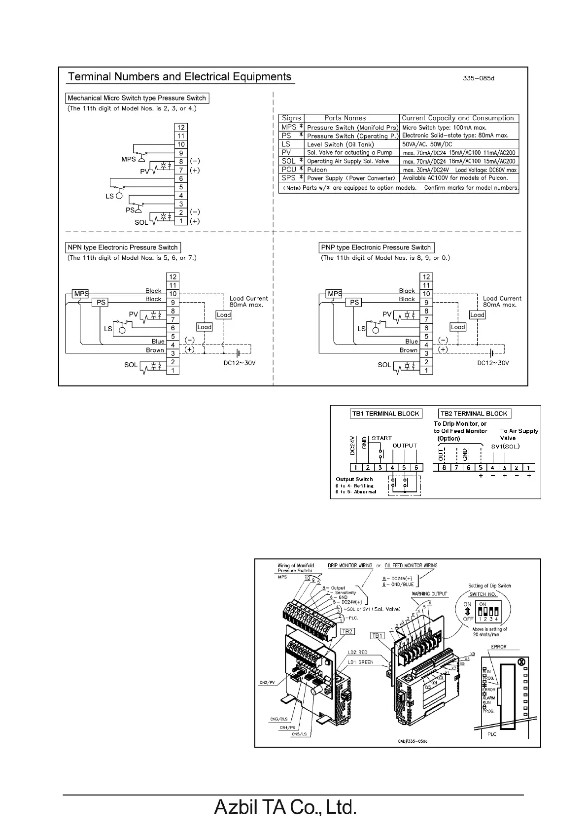
circuit (DC24V), connect electrical wiring for electric
supply, input for START, and alarming output to TB1
terminal of circuit board.
・Refer to page 22 for electrical wiring of MC9 models
equipped with electrical control circuit.
・Connect DC24V electric supply to TB1 terminal block.
Terminal of 1 is for +24V, and of 2 is for GND.
・Connect alternate type switch for input of START between terminal of 3 and 4.
・Terminal of 4, 5 and of 6 are prepared for output of alarming signal. These outputs are by electrical
dry contact (no electric potential).
Terminal of 6 is for com contact point.
Terminal of 4 is for alarming of oil
replenishment, and terminal of 5 is
for alarming of abnormal operation.
In case of normal operating state, the
contact points are kept closed.
Equipment associated with these
contacts should be activated with
voltage below 60V.
・In case a solenoid valve (SV1: DC24V,
max 10W) instead of the valve
integrated to Filter-Regulator has
been prepared separately, connect
the prepared solenoid valve to terminal of 3(+) and of 4(-) of TB2 terminal block.
This solenoid valve is activated simultaneously at the time when the electric power is supplied.
 Loading...