2
■ Panel mounting procedure
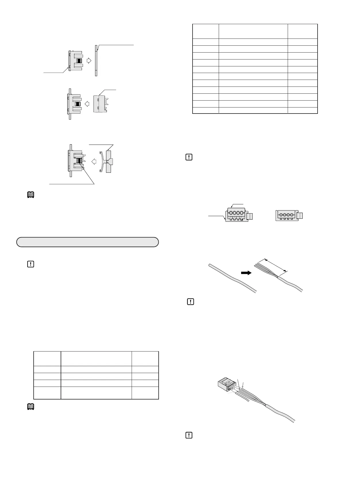
(1) Insert the mounting part into the panel hole to firmly
fix it to the panel.
(2)
Insert the main unit into the back of the mounting part.
(3) After completing step (2), insert the mounting retain-
er from the back so that it engages the groove of the
mounting part.
Note
• To take the MCW400A100 off the panel, first
remove the mounting retainer with a screwdriver,
and then disassemble in the reverse order of
assembly.
■ Connector and wiring
Handling Precautions
• Do not apply excessive force, vibration, or
impact to the connectors or cables. Doing so
might cause equipment failure.
• When using a switching regulator for the
power supply, be sure to ground the frame
ground.
• When using any device (switching regulator,
inverter motor, etc.) that produces electrical
noise near the flow sensor, be sure to ground
the frame ground of the device.
● Flow sensor connector and wires
Note
• Lead wire for trigger signal for memorizing
reference flow value must be supplied by the
customer. Wire size is 0.14 to 0.3mm
2
and outside
diameter of the insulator is 0.8 to 1.0mm.
● I/O connector and wires
● Connecting the cable of the flow sensor
The cable of the flow sensor is not yet connected to
the connector (pin contacts). Follow the steps below
to connect the cable and connector.
Handling Precautions
• Make sure that the connector cover (lead wire
insertion part) stands above the connector
main body as shown in the figure below. If the
connector cover is not lifted off the connector
main body, it cannot be used.
(1) Cut the cable to the required length. Remove the
sheath approx. 50mm from the end to free the lead
wires. However, do not remove the insulation from
the lead wires.
Handling Precautions
• The insulation at the end of the flow sensor
wire is incised at the factory. Cut off this por-
tion of the wire before inserting the leads into
the connector.
(2) Insert the lead wires into the holes in the connector
cover so that the lead wire colors and pin Nos. match
those indicated on the connector. Check through the
top of the semitransparent cover that the lead wires
are fully inserted to the end. (The insertion length is
approx. 9mm.)
Handling Precautions
•Ifreference flow value is desired, be sure to
insert that lead wire into the connector cover
before crimping.