6
●
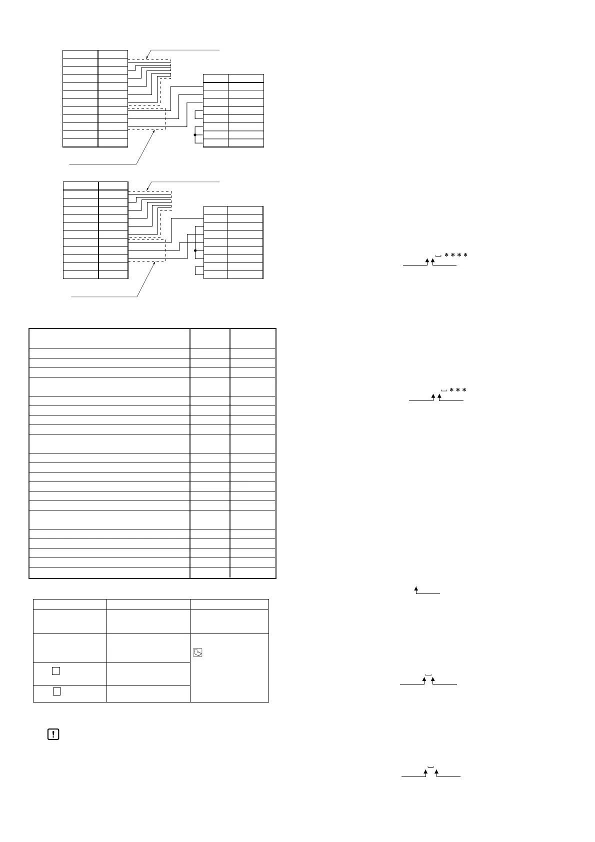
Communications cable specification and connection
■ Function list
● Error indication and correction
● Communications commands
Handling Precautions
• Underscores ( ) in the send examples stand
for spaces.
• The following example shows a response if an
error occurs.
NG (CR/LF)
21:illegal type
@
A
Function: Reads out the current flow rate
(channels 1-4).
Command example
: @A (CR/LF)
Response example
: 1=-3.00 (CR/LF) 2=3.00 (CR/LF)
(CR/LF)←
This shows that no sensor is
connected to ch. 3.
4=0.00 (CR/LF)
(CR/LF)
@
PRE
Function:
Sets the ON/OFF point for any channel.
Command example
: @PRE11 -3.00 (CR/LF)
Response example
: OK (CR/LF)
@
PRE11: Channel 1, L1/∆L setting
@
PRE12: Channel 1, L2 setting
@
PRE21: Channel 2, L1/∆L setting
@
PRE22: Channel 2, L2 setting
@
PRE31: Channel 3, L1/∆L setting
@
PRE32: Channel 3, L2 setting
@
PRE41: Channel 4, L1/∆L setting
@
PRE42: Channel 4, L2 setting
@
HYS
Function: Sets the hysteresis width for any
channel.
Command example
: @HYS11 0.02 (CR/LF)
Response example
: OK (CR/LF)
@
HYS11: Channel 1, hysteresis width setting
@
HYS21: Channel 2, hysteresis width setting
@
HYS31: Channel 3, hysteresis width setting
@
HYS41: Channel 4, hysteresis width setting
@
P
Function:
Sets trigger signal for memorizing
reference flow value is enabled or not,
when window comparator mode 2 or 3
is selected as the operation mode.
Command example
:@P1 (CR/LF)
Response example
: OK (CR/LF)
@
P1: Trigger signal for memorizing reference flow value
is enabled at channel 1
@
P2: Trigger signal for memorizing reference flow value
is enabled at channel 2
@
P3: Trigger signal for memorizing reference flow value
is enabled at channel 3
@
P4: Trigger signal for memorizing reference flow value
is enabled at channel 4
@
MODE
Function: Sets the operation mode for any
channel.
Command example
: @MODE1 1 (CR/LF)
Response example
: OK (CR/LF)
@
TYPE
Function: Sets the flow sensor type for any
channel.
Command example
: @TYPE1 1 (CR/LF)
Response example
: OK (CR/LF)
1: Ch. 1
2: Ch. 2
3: Ch. 3
4: Ch. 4
1: Ch. 1
2: Ch. 2
3: Ch. 3
4: Ch. 4
1: Ch. 1
2: Ch. 2
3: Ch. 3
4: Ch. 4
1: Ch. 1
2: Ch. 2
3: Ch. 3
4: Ch. 4
1: Ch. 1
2: Ch. 2
3: Ch. 3
4: Ch. 4
or the cable.
comparator mode 2 or 3.
(channels 1-4).
Pin No.
Pin No.
Pin No.
Pin No.
Function Key RS-232C
operation command
Instantaneous flow rate indication
Yes
@A
L1 (∆L) / (L2) settings
Yes
@PRE
Hysteresis settings
Yes
@HYS
Trigger signal for memorizing
Yes
@P
reference flow value
Operation mode selection
Yes
@MODE
Flow sensor selection
Yes
@TYPE
Zero reset setting
Yes
@B
Auto-scanning indication
Yes
@AS
Output mode setting
Yes
@INV
(only for comparator mode 4)
Peak hold setting
Yes
@PHL
Bottom hold setting
Yes
@BHL
Indication on/off
Yes
@DIS
Operation mode confirmation No @MD
Flow sensor type confirmation No @TP
L1 / L2 confirmation No @C
Threshold flow value confirmation No @E
(only for modes 2 and 3)
Output status confirmation No @SW
Switch output response time setting
Yes
@DLY
Switch output response time confirmation No @SD
Flow rate display moving average setting
Yes
@FIL
Flow rate display moving average confirmation
No @F

 Loading...


