(3) Carefully squeeze the cover and connector main
body together with an appropriate hand tool, such as
pliers so that no lead wires are disconnected from the
connector.
The crimping force must be 980.7N or less.
When the connector and cover top surfaces are level,
the connection work is complete.
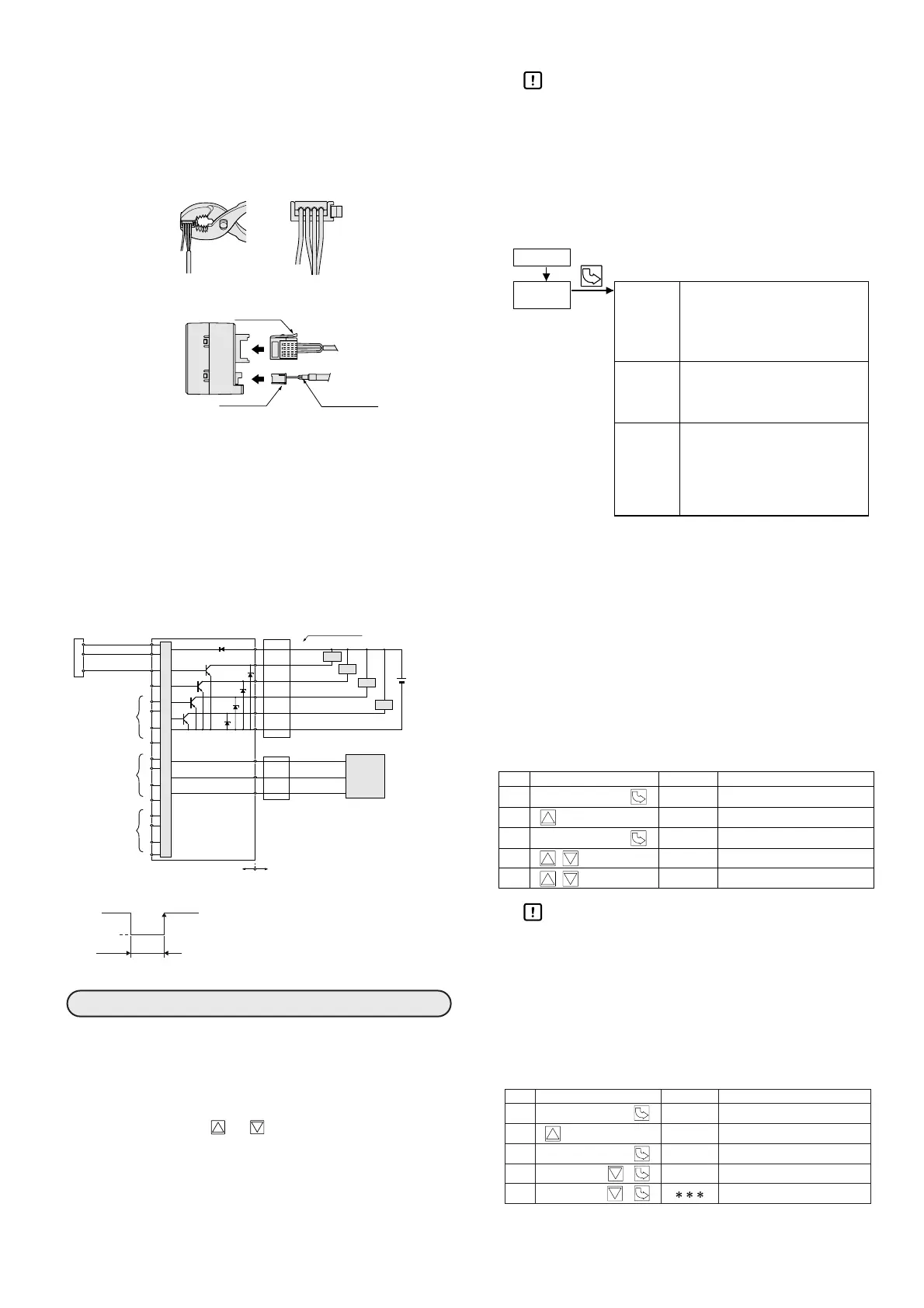
● Connecting and disconnecting the cable
(1) To connect the flow sensor cable and signal cable,
position the lock levers as shown in the figure above,
and insert the cable connectors until the locks are
engaged.
(2) To disconnect the cable, push down the lock lever
sufficiently, hold the connector, and pull the cable
out. Be especially careful that no excessive force is
applied to the lead wires.
■
Internal circuit and external wiring example
■ Operating
When the power is turned ON, this unit automatically
enters indication mode. In indication mode, the flow rate
of channel 1 is shown on the flow rate indicator and
channel indicator 1 is lit. The indicated channel can be
changed with the or key.
■ Setting
Handling Precautions
• Do not press the keys with a mechanical pen-
cil or other sharp-tipped object. Doing so
might cause damage.
When the mode key is pressed after the power has been
turned ON, the mode enters the setting mode. To change
the settings from the factory defaults, follow the steps
below.
● Factory settings (all 4 channels)
Flow range type: SE1 (MCS100A100)
Operation mode: CO1
(window comparator
mode 1)
Hysteresis: 0.02L/min
L1 level: 2.00L/min
L2 level: 1.00L/min
Switch output response time: 3 ms
Flow rate display moving average: Disabled
1. Indication settings
1-1 Auto-scanning indication
Auto-scanning indication at all channels is available.
Handling Precautions
• Since the auto-scanning mode is also used for
the key lock function, key operations other
than auto-scanning cancellation are not possi-
ble.
• When the power is turned OFF, the auto-
scanning mode is cancelled.
1-2 Manual flow
display on/off
The flow rate indication can be turned on and off.
Flow sensor ch. 1
Flow sensor ch. 2
Flow sensor ch. 3
Flow sensor ch. 4

 Loading...


