3-3
Output mode inverting (window comparator
mode 4 only)
The output of any channel can be inverted.
Output mode
inverting
S-0: Non-inverted (normally open)
S- 1: Inverted (normally closed)
Handling Precautions
• This function is disabled in any mode other
than window comparator mode 4.
3-4
Switch output response time setting
It is possible to set the amount of response time that
elapses (on-delay) until the switch output of a chan-
nel turns on.
Switch output response time setting
Sb- 1:
Disabled (3 ms or less)
Sb-3: 100 ms or less
Sb-2: 20 ms or less Sb-4: 1000 ms or less
■ Operation mode
● Window comparator mode 1
L1 and L2 can be set to desired levels. If the flow rate
is increasing, SW output is not turned ON.
● Window comparator mode 2
L1 is automatically set according to the ∆L setting
and reference flow value (L1 = "reference flow
value" - ∆L). If the flow value is increasing, output
is not turned ON.
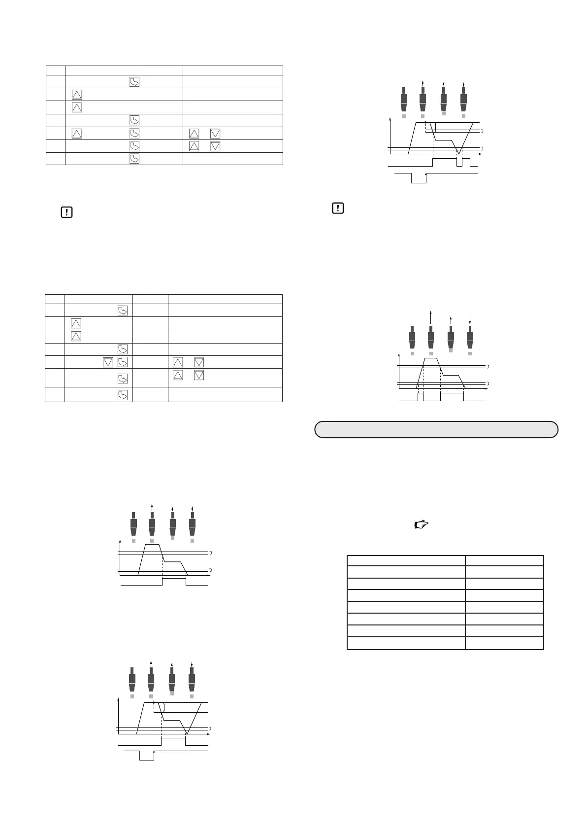
● Window comparator mode 3
L1 is automatically set according to the ∆L setting
and reference flow value (L1 = "reference flow
value" - ∆L).
Handling Precautions
• Do not input a trigger signal for memorizing
reference flow value frequently in window
comparator mode 2 or 3. Doing so might
cause the number of EEPROM erase-write
cycles to exceed the guaranteed amount.
● Window comparator mode 4
L1 and L2 can be set to desired levels.
● Hardware requirement
PC: PC-98 series or equivalent DOS/V machine
OS: Windows 95 or later
● Software requirement
HyperTerminal, a standard accessory of Windows 95
or later, is used. For details about how to set up
HyperTerminal, Page 8.
● Communications parameters
Item Contents
Transmission speed 9600bps
Stop bits 1bit
Parity Odd
Parity check Yes
Data bit length 8 bits
Communications method Full duplex
Return key send procedure CR/LF codes
7-seg. LED
7-seg. LED