5-82
Chapter 5. DETAILED DESCRIPTION OF EACH FUNCTION
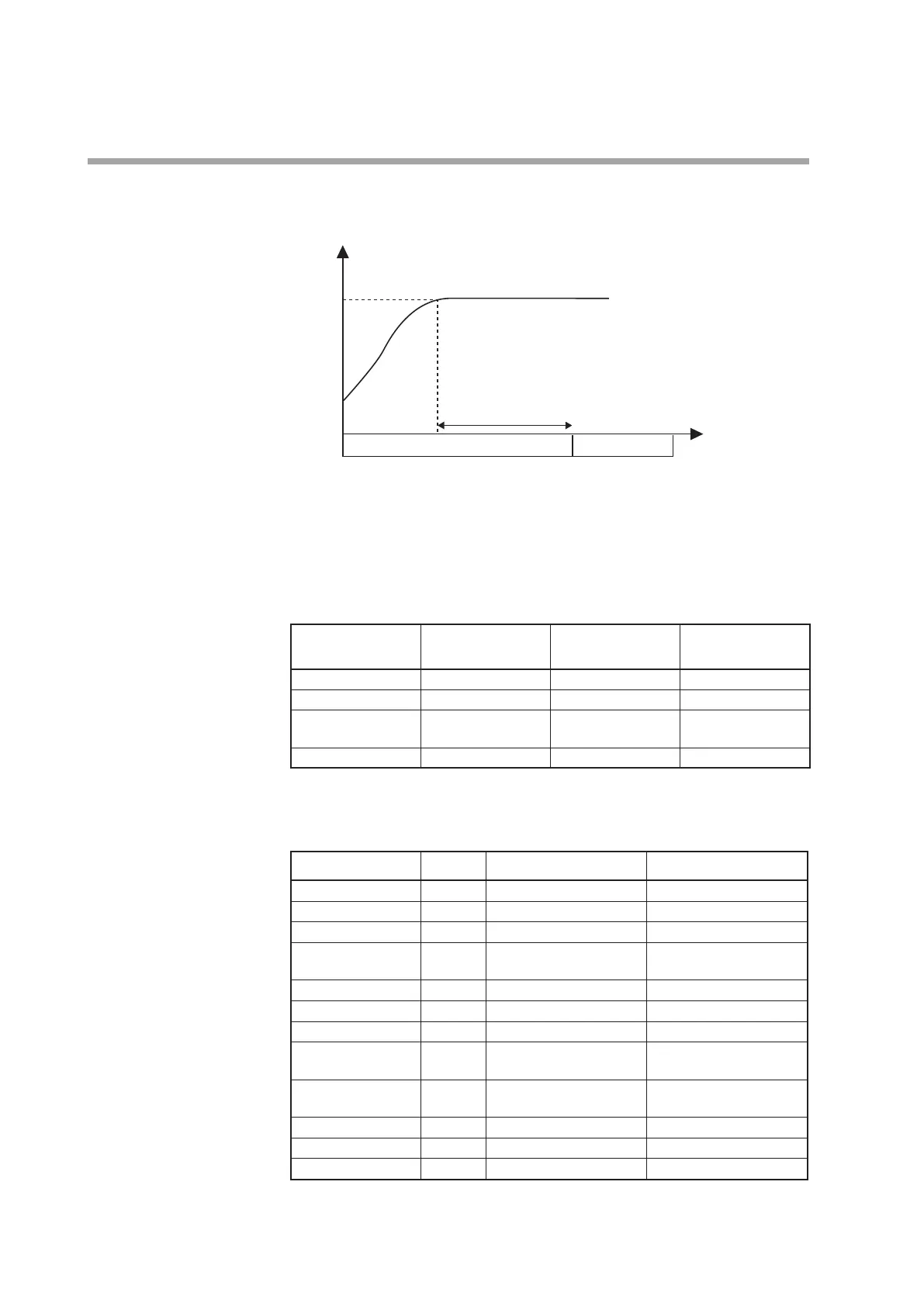
Example 2 The operation is started by the external switch, and then it is stopped automatically
30min after the temperature has reached the set value.
Time
30 min
Control ON Control OFF
Explanation
The timer start-up conditions are set to logical AND of DI1 and PV status EVs.
The ON delay timer setting decides the time period after which the operation is
stopped automatically when the temperature has reached the set value.
The mode (RUN/READY) is changed based on a combination of DI1 and timer
ON-OFF.
Status Control OFF status
Timer counting after
starting of operation
Operation stop by
time-up
DI1 OFF ON ON
Timer (Internal EV2) OFF OFF ON
Status of Internal
Contact 2
ON OFF ON
Mode READY RUN READY
Setting example
• Event
Event Display Internal Event 1 Internal Event 2
Operation type
E
_
.C1
32: Timer 4: Deviation high limit
Direct/reverse
E
_
.C2
---- 0: Direct
Standby
E
_
.C2
---- 0: No standby
EVENT state at
READY
E
_
.C2
0: EVENT state at READY is
continued.
0: EVENT state at READY is
continued.
Alarm OR
E
_
.C3
0: None 0: None
Special OFF setup
E
_
.C3
---- 0: As usual.
Delay time unit
E
_
.C3
2.1min 0: 0.1s
Event main setting
(low limit)
E
_
---- 0
Event sub-setting
(high limit)
E
_
.SB
---- ----
Hysteresis
E
_
.HY
---- 5
ON delay
E
_
.ON
30 0
OFF delay
E
_
.OF
0 0
Note. The internal event No. is indicated at the mark of "_" shown in the display
column.