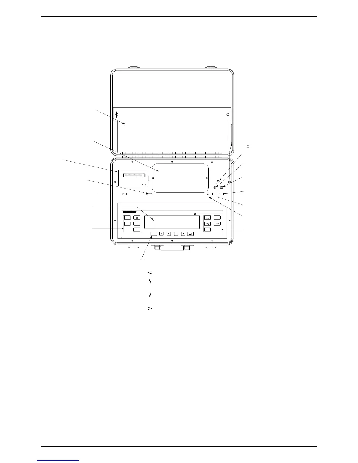
RS 232
POWER
OPT
T-STACK T-AIR
PRESSUREGAS
P REF
ECA 450
SET UP
CALIBRATE
MEMORY
FUEL
MENU
PRINT
POWER
I/O
RUN
SAVE
ENTER
V
ESC
PRESSURE
PRINT
– Prints contents of either the
Combustion Test or Pressure screen
on local printer.
SAVE – Saves to memory the contents
of the Combustion Test or Pressure
screen. Saved data can later be
recalled for viewing on the display, or
downloaded to a personal computer.
MENU
– Steps display from the
Combustion Test screen through the
Setup List, Calibrate, Fuel, Pressure,
and Memory menu screens.
Alternately, a particular menu screen
can be directly displayed by pressing
its associated shortcut key.
I/O
– Turns analyzer ON and OFF.
RUN – Starts and stops a combustion
efficiency test.
SET UP
– Displays Setup List
screen.
CALIBRATE
– Displays Calibrate
screen.
FUEL
– Displays Fuel screen.
PRESSURE – Displays Pressure
screen.
MEMORY – Displays Memory
screen.
ESC
– Displays previous menu or previously
viewed screen.
– Moves cursor left.
– Moves cursor up through screen, or
increments an alphanumerical value.
– Moves cursor down through screen, or
decrements an alphanumerical value.
– Moves cursor right.
ENTER – Chooses a menu item that has been
selected by the cursor's position.
VACUUM FLUORESCENT
DISPLAY PANEL
(4 Lines by 20 Characters)
PRINTER
BATTERY CHARGER/
AC ADAPTER CONNECTOR
RS 232 CONNECTOR
P REF
– Differential pressure
reference hose connector
GAS – Probe's stack hose connector
PRESSURE – Probe's draft hose
connector
T-STACK – Probe's Flue-gas
thermocouple connector
T-AIR
– Primary air thermocouple
connector
OPT
– Option connector
STORAGE COMPARTMENT
6" x 18" x 3"
SENSOR COMPARTMENT
SHORTCUT MENU KEYS:
P / P