4
PLUG-AND-PLAY CIRCUIT BOARD
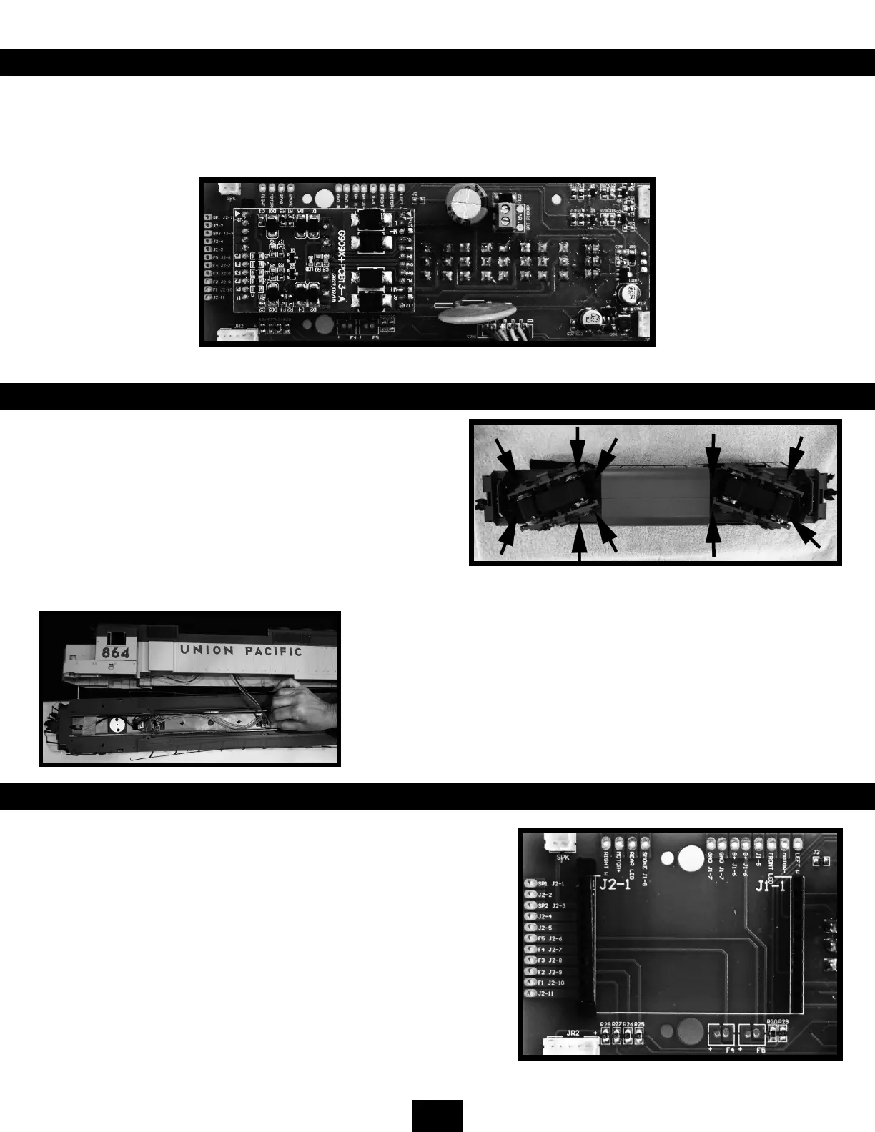
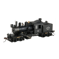
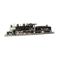
This Bachmann GP40 locomotive comes equipped with a nonproprietary plug-and-play electronic circuit board. This is
designed to accommodate your chosen aftermarket plug-and-play products. As delivered, the locomotive has a (DC) Jumper
PC Board in this socket and will operate on standard DC-powered track setups without modication. All of the locomotive’s
lighting functions are on when the (DC) Jumper PC Board is in the socket and the LIGHT switch is ON.
REMOVING THE BODY SHELL TO ACCESS THE ELECTRONICS
To reach the speaker and PC board, it is necessary to separate
the underframe from the body of the locomotive. The body shell
is secured to the underframe with 10 Philips-type screws. See the
photo below. The black arrows indicate the locations of the screws.
Once the screws are removed, turn the locomotive over and
remove the handrails from both sides of the cab. Once removed,
gently lift the body shell from the locomotive frame. Unplugging
the two plugs between the frame and the body will allow you
greater access to the shell.
Care should be taken to not damage fragile detail parts such as the steps
when handling and turning the locomotive on its roof. The use of a padded
locomotive cradle is recommended.
Gently unplugging the wire cable between the locomotive’s body shell and
the under frame will allow you to move the shell to your workbench for
greater access to the interior of the shell.
PIN DEFINITIONS
Each pin on the plug-and-play circuit board has a dened purpose as
shown in the table on the following page. Each pin is also connected to
a solder pad for use with systems that do not support a plug-and-play
setup. The J1 solder pads are above the socket and the J2 solder pads
are on the left-hand side of the circuit board. The J2 row of pins has a
blank key on either end of the row to help ensure that a plug-and-play
device cannot be incorrectly inserted.
Front
Back