5
Pin number
J1
Purpose Pin number
J2
Purpose
12
Rail + Solid Key
11
Rail + 11 Not used
10
Motor + 10 Front Number Boards
9
Rear Locomotive Headlight 9 Cab Light
8
Smoke Unit 8 Porch Safety Lights
7
Locomotive Ground 7 User Installed Right Ditch Light
6
Locomotive Positive 6 User Installed Left Ditch Light
5
Not Used 5 Not Used
4
Front Locomotive Headlight 4 Not Used
3
Motor – 3 Speaker –
2
Rail – 2 Not Used
1
Rail – 1 Speaker +
Solid Key
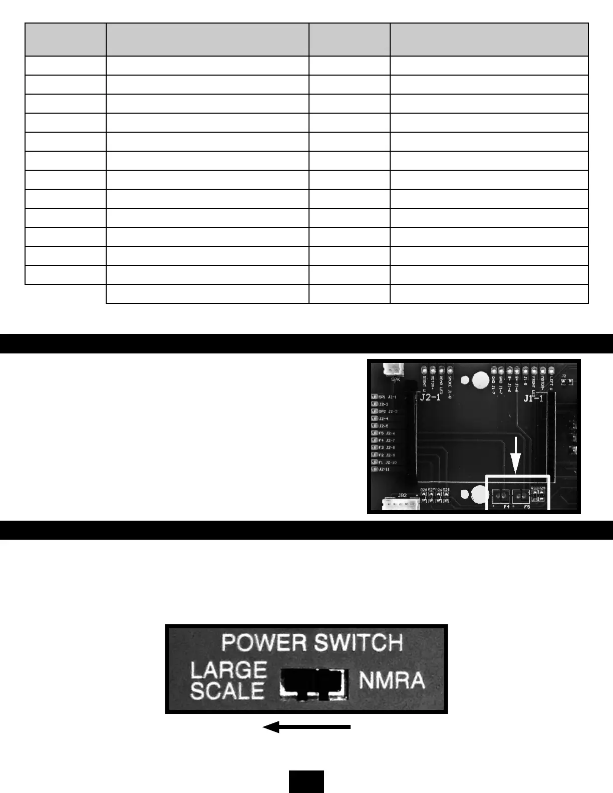
USER INSTALLED DITCH LIGHTS
Ditch lights came into frequent use in the 1980s and were mandated in
1997. Most GP40s came from the factory without ditch lights but as the
years progressed most railroads added them. The Bachmann GP40 has
provisions to easily add ditch lights should you desire. On one side of the
socket are two sets of solder pads labeled F4 and F5. Each set of pads has
one pad for connection to the ground side of an LED and a second pad for
the + side of the LED. The + side of these pads is protected with a limiting
resistor allowing a direct connection to an LED.
TRACK-POWERED DC OPERATIONS
To operate your locomotive using track power, leave the (DC) Jumper PC Board in place, make sure that the motor switch
is ON, the pickup switch is in the TRACK position, and the NMRA/Large Scale Polarity Switch is set for its correct position
(normally the LARGE SCALE position for compatibility with G scale equipment from other manufacturers). In this mode, the
locomotive’s headlight and markers will be direction-dependent.