6
ADDING AN AFTERMARKET SOUND SYSTEM
This locomotive has a speaker mounted underneath the radiator grille. If your sound
system is designed for plug-and-play operation, remove the (DC) Jumper PC Board
and plug in your sound system. If your sound system does not provide plug-and-play
operation, continue to use the (DC) Jumper PC Board and connect the sound system
wires to the solder pads labeled Right W and Left W on the right-hand side of the
main PC board.
Please note: To ensure proper operation, any device connected to the circuit board
should have its ground connection made to the locomotive’s ground using one of
the GND J1-7 pins.
ADDING AFTERMARKET TRACK-POWERED NMRA DCC CONTROL
If your NMRA-compliant DCC decoder is designed for full plug-and-
play operation with the plug-and-play circuit board, remove the (DC)
Jumper PC Board and replace it with your plug-and-play decoder.
If your decoder is not designed for full plug-and-play operation, use
the supplied Jumper PC Board with wires (shown here) and attach the
wires to your decoder following the instructions that came with your
decoder. Note: the decoder’s + and – outputs must be connected
to the Jumper PC Board’s GND and B+ wires to allow the internal
lighting to function properly. Holes are provided on the main circuit
board near the center of the socket to allow the installation of a zip
tie to hold the boards together.
ADDING AFTERMARKET ON-BOARD BATTERY/RC OPERATION
If your Battery/RC or DCC Direct (wirelessly transmitted DCC) system supports plug-and-play using the plug-and-play circuit
board, remove the (DC) Jumper PC Board on the circuit board and replace it with the plug-and-play board of your choice.
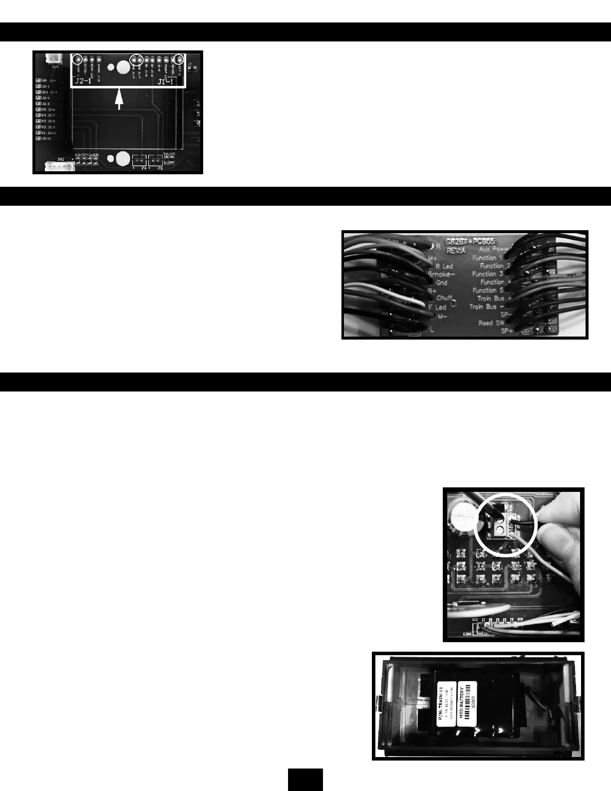
Connect the batteries to the Bat Pickup screw terminals on the locomotive’s main circuit board and switch the Track/Battery
pickup switch to BATTERY. Note: If your Battery/RC or DCC Direct system does not provide DC power to the locomotive’s
ground and B+ connections then it will be necessary to also connect the battery to the J1-7 GND and J1-6 B+ connections
to power the locomotive’s internal functions. If you wish to house your batteries on the model, you can install them in the
locomotive’s shell or the fuel tank underneath the locomotive. A convenient hole is provided to allow the wires from a battery
in the fuel tank to be connected to the main board. When installing a larger battery in the
fuel tank, it may be necessary to remove the plastic center support.
You can also install your batteries in a separate trailing car and connect them to the
locomotive using the power plugs next to the front and rear couplers.
If your Battery/RC system does not support plug-and-play operation, use the supplied
Jumper PC board with wires and attach the wires to your Battery/RC or DCC Direct system
following the instructions that came with your system.
Please note: The Battery/RC system’s + and - outputs must be connected to the Jumper PC
Board’s GND and B+ wires to allow the internal lighting system to function properly. Holes
are provided on the main circuit board near the center of the socket to allow the installation
of a zip tie to hold the boards together.
The NMRA/Large Scale Polarity Switch works in both track and battery
modes. In BATTERY mode, the battery terminals are connected to the Rail +
and Rail - terminals on the circuit board (J1-1, 2 and J1-11, 12). The polarity
of these terminals can change by the position of the NMRA/Large Scale
Polarity Switch. This means that any device plugged into the plug-and-play
circuit board must protect itself from polarity reversals either through a diode
or a rectier. Please refer to your after-market owner’s manual for proper
installation.
Battery Installed in Fuel Tank
 Loading...