Do you have a question about the Backyard Discovery SOMERVILLE and is the answer not in the manual?
Section for recording purchase, installation, and tracking details for warranty claims.
Details customer costs for part replacements based on product age, covering different part types.
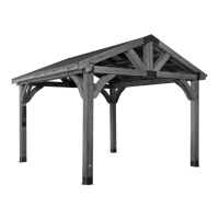
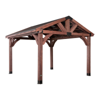
Explains the type of wood used (Cedar) and its natural susceptibility to weathering.
Details how moisture and climate affect wood, causing checking, warping, and fading.
Provides methods to protect the wood, including yearly sealant application and light sanding.
Advice on avoiding exposed bolt threads and proper hardware usage to prevent protrusions.
Guides for correct bolt, T-nut, barrel nut, and lag screw assembly techniques.
Instructions for organizing wood components by part number before assembly for efficiency.
Guidance on organizing hardware bags by part number or type for easier assembly.
Explains the meaning of various icons used throughout the manual for assembly guidance and warnings.
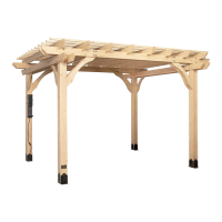
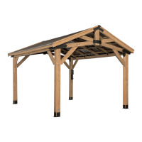
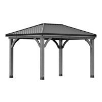
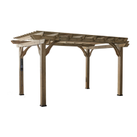
Provides the total external dimensions of the pergola structure in feet and meters.
Details the space required on the ground for the pergola's base footprint in feet and meters.
Lists and illustrates all wooden parts with their identifiers, dimensions, and quantities.
Lists and illustrates all hardware fasteners and tools required for assembly, with part numbers.
Lists and illustrates additional components like post feet, ID tags, and electrical enclosures.
Assembling joist ends with pergola posts and angle braces using specified hardware.
Connecting inner joists to angle braces and pergola posts using bolts and nuts.
Assembling outer joists to angle braces and pergola posts using specified hardware.
Attaching assembled joist assemblies to upright posts using bolts, lag screws, and nuts.
Securing slotted joists to the outer joists using lag screws and washers.
Alternating and attaching P01 and P02 purlins to the joist boards using screws.
Positioning pergola feet and ensuring posts are square on the foundation surface.
Using chalk to trace the outline of each foot for precise placement on the foundation.
Drilling pilot holes and securing feet to the concrete pad using provided anchors.
Placing pergola posts into feet and securing them using screws.
Centering and mounting revision and ID tags on the pergola posts at a specified height.
Mounting the electrical enclosure to the pergola post according to specific instructions.
Provides caution regarding modifications and guidelines for correcting radio frequency interference.
| Brand | Backyard Discovery |
|---|---|
| Model | SOMERVILLE |
| Category | Outdoor Furnishing |
| Language | English |