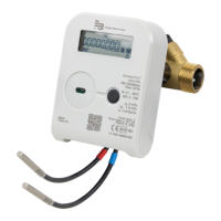
The Dynasonics UHC100 is an ultrasonic heating and cooling energy meter designed for commercial metering of consumed energy in individual or district heating facilities where water is the heat carrier. This compact microprocessor meter measures and records heating and cooling energy consumption in two separate registers. It can be mounted at either the supply or return heat exchange circulation system and includes permanently connected temperature sensors. The meter complies with the requirements of Annex 1, Annex M1004 to the Technical Regulation on Measuring Instruments and harmonized standards LST EN 1434, meeting Environmental Class C according to LST EN1434-1:2016. It is also approved by Measurement Canada for thermal energy metering in residential, commercial, industrial, and institutional heating systems.
Function Description
The UHC100 operates on the ultrasonic measurement principle for flow rate, sending ultrasonic signals upstream and downstream between sensors. The flow rate is calculated based on the measured propagation time difference. Temperature differential between supply and return flows is measured by resistive temperature sensors. The electronic unit calculates consumed heat energy by integrating the difference of enthalpies of supply and return heat carrier over time, displaying the data. When the cooling energy tariff function is activated, energy is accumulated in an additional tariff register for negative temperature differentials.
The electronic unit performs various functions:
- Measures heat energy and determines overload characteristics.
- Calculates and stores maximum values.
- Stores daily, yearly, and monthly data for reports.
- Measures consumption under tariffs.
- Stores 36-month values, including calculated energy, volume, and tariff register.
- Detects and displays errors.
- Displays values, parameters, and error codes.
- Performs test and service functions.
Important Technical Specifications
Energy Measurement:
- Accuracy Class: 2 (according to LST EN1434-1:2016; Class 2 Measurement Canada).
- Energy Measurement Units: kWh, MWh, GJ, Gcal.
- Maximum Thermal Power: 5.28 MW.
Flow Measurement:
- Ratio of permanent flow rate to lower limit (qp/q₁): 100 or 250 (selectable).
- Flow Sensor Accuracy: Class 2.
- Heat Conveying Liquid: Water.
- Ambient Temperature: 41...131° F (5...55 °C).
- Relative Humidity: <93%.
- If flow rate exceeds 1.2 times the maximum flow rate (qs), calculations continue using 1.2 qs, and an "exceeded maximum flow rate" error is recorded.
- Number of Pulse Inputs: 2.
- Indicated Units: m³.
- Pulse Value: Programmable.
- Input Pulse Types: IB according to LST EN1434-2.
- Max. Permissible Frequency: 3 Hz.
- Max. Permissible Voltage: 3.6V.
- High Level Maintenance Condition: 3.6V through 3.3 MΩ resistor.
- If ordered with "pulse input-output" function, a permanently connected 1.5 m cable is fitted.
Temperature Measurement:
- Temperature Measuring Range: 32...194° F (0...90 °C) or 32...266° F (0...130 °C) (custom-made).
- Temperature Difference Measuring Range: 2...70 K or 3...70 K (custom-made).
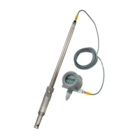
- Temperature Sensor Design: DS type (for G3/4, G1, G1-1/4 flow sensor connections) or PL type (for other flow sensor connections).
- Connected Cable Length: Up to 33 ft (10 m).
- Temperature limits of heat conveying liquid: 32...194° F (0.1...90° C) for custom-made, wall-mounted electronic unit; 32...266° F (0.1...130° C) for custom-made.
- Length of connecting cable between flow sensor and electronic unit: 4 ft (1.2 m) or 8 ft/16 ft (2.5 m/5.0 m) (custom-made).
Display:
- Liquid crystal, 8-digit display with special symbols for parameters, units, and operating modes.
- Displays integral and instantaneous measured parameters, archive data, and configuration information.
- Energy Measurement Units: kWh, MWh, Gcal, or GJ (user-selectable).
- Resolution of Energy Indicators: 0000000.1 kWh, 00000001 kWh, 00000.001 MWh (Gcal or GJ), 000000.01 MWh (Gcal or GJ).
- Resolution of Flow-Rate Indicators: 00000.001 m³.
Data Recording and Storage:
- Archives hourly, daily, and monthly parameters.
- Minimum Archive Capacity: 1480 hours, 1130 days, 36 months.
- Archive Data Storage Time: At least 36 months.
- Storage of all measured integral data (without power supply): At least 15 years.
External Communication Interfaces:
- Optical interface (always included).
- Ordered interfaces (selectable): M-Bus interface, RF 868 MHz interface.
- Wired interfaces include a permanently connected 5 ft (1.5 m) length cable.
- Communication is automatically limited to save battery life (16 hours/month average) if powered by internal battery.
Pulse Outputs:
- Number of Pulse Outputs: 2 or none (specified when ordering).
- Class: OB in Operating Mode, OD in Test Mode.
- Type: Open collector.
- Permissible Current: Up to 20 mA.
- Voltage: Up to 24 V.
- Pulse Duration: 125 ms in Operating Mode; 1.2 ms in Test Mode.
Meter Power Supply:
- One or two internal AA-size 3.6 V lithium (Li-SOCl2) batteries (service life 15+1 years).
- External 12...42V DC or 12...36V 50/60 Hz AC voltage (consumption current < 20 mA).
- External 230V 10...15% 50/60 Hz AC voltage (consumption current < 5 mA).
Operating Conditions:
- Electronic Unit Protection Class: IP65 (IP67 or IP68, custom-made).
- Flow Sensor Protection Class: IP65 (IP67 or IP68, custom-made).
- Temperature Sensors Protection Class: IP68.
- Ambient Temperature: 5...55° C.
- Relative Humidity: Up to 93%.
- Atmospheric Pressure: 86...106.7 kPa.
- Mechanical Environment Class: M1.
- Electromagnetic Environment Class: E2.
Usage Features
Installation:
- Meters must be installed by qualified specialists according to documentation and design.
- Signal wires should not be laid closer than 2 in. (5 cm) from power cables.
- Meter configuration (supply/return pipe, heat/cooling energy, units, resolution, tariff registers, pulse inputs/outputs, reporting date, subscriber number, clock time, M-Bus addresses/speed) must be verified and adjusted if necessary.
- Transport mode turns off automatically after 1 liter of volume accumulation or by button/software.
- Electronic unit (calculator) should be mounted in a heated room, not exceeding 131° F (55° C), away from direct sunlight, heat-emitting devices, or strong electromagnetic fields. It can be mounted on an auxiliary holder, directly on the flow sensor housing (if flow temperature < 194° F (90 °C)), on a wall, or on a DIN rail in an electrical cabinet.
- Flow sensors can be installed horizontally, vertically, or on a slope, ensuring the pipe is fully filled with water and pressure is at least 30 kPa. Flow direction must match the arrow on the sensor. Straight sections are required for DN65, DN80, and DN100 sensors (5 pipe diameters upstream, 3 downstream). No straight sections are needed for other connection types.
- Temperature sensors should be installed with placement heads upward, perpendicular to the pipe axis or at a 45° angle, with the sensing element immersed to the pipe centerline. One temperature sensor is installed in the flow sensor housing for G3/4, G1, and G1-1/4 flange types. Wires should be kept at least 2 in. (5 cm) from power cables.
Operating Procedure:
- Data is displayed on an 8-digit LCD. The control button on the electronic unit selects measured and information data.
- Symbols indicate flow direction (right arrow for right, left arrow for opposite, no arrow for no flow), meter configuration (supply or return line), and significant errors.
- The display shows integral and instantaneous parameters (INT), monthly archives and reporting day data (BIL), and configuration information (INF).
- The main integral readings or errors are shown if the button is not pressed for more than 60 seconds.
- Parameters can be changed using HEAT3_service software or buttons in transport mode. If transport mode is off, parameters (except energy measurement type, units, and installation place) can be changed by short-circuiting SERVICE contacts.
Test Mode:
- Test Mode (TEST) is for quick testing and can be activated via the control button, optical interface, or jumper.
- In Test Mode, the meter displays increased resolution energy and flow values, forms energy or volume pulses through the optical interface, and forms energy/volume pulses at pulse outputs.
- Water volume simulation is possible when Test Mode is activated by short-circuiting SERVICE contacts.
- Activation via the control button requires selecting "tESt On Wh" or "tESt On m³" and entering a four-digit password (default: 0001).
- Test Mode can be deactivated by selecting "tESt OFF" and holding the button, or it deactivates automatically after 12 hours.
Maintenance Features
Unpacking and Inspection:
- Visually inspect the product and accessories for physical damage upon receipt.
- Report any damage to the carrier's agent within 48 hours and file a claim.
Safety:
- Installation must comply with federal, state, and local rules.
- Do not use sharp objects on the keypad.
- Ensure proper earthing to prevent electric shock and data loss.
- Disconnect from mains and delay 5 minutes before opening.
- Only qualified personnel should install/repair the product.
- Do not place units on unstable surfaces or above radiators.
- Route cabling away from hazards.
- Clean with a damp cloth; do not use liquid or aerosol cleaners.
- If faults occur, disconnect from power supply and contact a qualified service person.
Transportation and Storage:
- Transport in covered vehicles, securely fastened to prevent shocks or movement.
- Protect against mechanical damage.
- Store in rooms free from aggressive, corrosive materials.
- Storage conditions: -13...95° F (-25...35° C), max. 60% humidity.
Marking and Sealing:
- The electronic unit's front panel indicates manufacturer, type, certificate number, factory number, year of manufacture, temperature ranges, accuracy, environmental class, flow measurement range, communication interfaces, and supply voltage.
- The flow sensor housing indicates connection type and flow direction.
- Wire communication interfaces, inputs/outputs, and external power cables are marked with color and labels.
- Temperature sensors for higher temperature pipelines are marked with a red sign; for lower temperature pipelines, a blue sign.
- After configuration or adjustment, opened slots must be sealed with sticker seals (LOCK, SERVICE, ADJ).
- The manufacturer's warranty sticker seal should be attached to the protective cap fastening screws of the flow sensor.
- Temperature sensor fastening screws should be sealed with mounting seals after installation.
Battery Disposal:
- Batteries must be disposed of according to local legislation (EU directive 2006/66/EG).