EasyManua.ls Logo

Badger Meter Dynasonics TFX-500w - User Manual

Badger Meter Dynasonics TFX-500w
4 pages
Print Icon
To Next Page IconTo Next Page
Loading...
INTRODUCTION
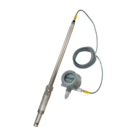
This document explains how to install small pipe transit time
ultrasonic integral transducers and transducers with remote
mounting. The transducers can be installed vertically
or horizontally.
The transducers have integrated transmitter and receiver
elements that eliminate the requirement for spacing
measurement and alignment.
PREINSTALLATION
REQUIREMENTS
Program the Meter
Before the flow meter will be operational, you must select the
optimum transmission mode, enter the site information, and
enter the uid and pipe properties into the ultrasonic flow
meter. For detailed instructions, see the user manual for your
flow meter.
Select a Pipe Location for the Transducers
Select a location for the transducers on a section of pipe that
has at least 10 pipe diameters upstream of the transducers
and 5 pipe diameters downstream. See “Figure 2: Piping
configuration and transducer positioning” on page2.
For example, if a 2 in. pipe is being measured, the minimum
upstream pipe in front of the transducer should be 20 in.
and the minimum downstream pipe behind the transducer
should be at least 10 in.
Pipe runs shorter than the minimums may sometimes be
used with reduced accuracy. There is no way to determine
how much accuracy is sacrificed without doing
in-field testing.
For installations where the 10/5 pipe diameters rule cannot
be followed, divide the total length of available straight pipe
into thirds and mount the rail with 2/3 of the pipe upstream
and 1/3 of the pipe downstream.
A full pipe is absolutely essential for making accurate flow
measurements. The flow meter cannot determine if the pipe
is full or not. If the pipe is partially full, the meter will
over-report the amount of flow by the percentage of the pipe
that is not filled with liquid or may not detect any flow.
Install the mounting system in an area where the transducers
will not be inadvertently bumped or disturbed.
Avoid installations on downward flowing pipes unless
adequate downstream head pressure is present to overcome
partial filling of—or cavitation in—the pipe.
YES
45°
45°
YES
45°
45°
Top of
Pipe
45°
45°
YES
YES
45°
45°
Top of
Pipe
U-Bolt
Split Housing
Figure 1: Transducer positioning
Transducers
Small Pipe, Fixed Size Transit Time Ultrasonic Transducers
IND-UM-02649-EN-05 (March 2021)
Installation Guide

Questions and Answers

Overview

The Dynasonics Small Pipe, Fixed Size Transit Time Ultrasonic Transducers are designed for accurate flow measurement in small pipe applications. These transducers are part of an ultrasonic flow meter system and are specifically engineered for ease of installation and reliable performance.

Function Description

The primary function of these transducers is to measure the flow rate of liquids within small pipes using the transit time ultrasonic principle. They operate by sending and receiving ultrasonic signals through the fluid in the pipe. The time difference between the upstream and downstream signals is then used to calculate the fluid velocity and, consequently, the flow rate. A key feature of these transducers is their integrated transmitter and receiver elements, which eliminate the need for separate spacing measurements and alignment during installation, simplifying the setup process. They are designed for use with a flow meter that processes the transducer signals to provide operational data. The system requires the user to program the meter with optimum transmission mode, site information, and fluid/pipe properties before it becomes operational.

Usage Features

Installation Flexibility: The transducers can be installed both vertically and horizontally on pipe sections. For horizontal pipes, the cable should exit at ±45 degrees from the side of the pipe, avoiding top or bottom exits. For vertical pipes, the orientation of the cable exit does not matter. The mounting system is designed to be installed in an area where it will not be inadvertently bumped or disturbed.

Pipe Size Compatibility: These transducers are fixed to specific pipe sizes ranging from 1/2 inch to 2 inches. It is crucial not to attempt mounting them on pipes that are too large or too small for the transducer to ensure proper function and accurate readings.

Piping Configuration Requirements: For optimal accuracy, the transducers should be installed on a straight section of pipe with at least 10 pipe diameters upstream and 5 pipe diameters downstream. For example, a 2-inch pipe requires a minimum of 20 inches upstream and 10 inches downstream. While shorter pipe runs may be used, they can lead to reduced accuracy, which can only be determined through in-field testing. In situations where the 10/5 pipe diameter rule cannot be met, the total available straight pipe should be divided into thirds, with the rail mounted such that 2/3 of the pipe is upstream and 1/3 is downstream.

Full Pipe Requirement: A full pipe is absolutely essential for accurate flow measurements. The flow meter cannot detect if the pipe is partially full. If the pipe is not completely filled with liquid, the meter will over-report the flow by the percentage of the pipe that is not filled or may not detect any flow at all. Installations on downward-flowing pipes should be avoided unless sufficient downstream head pressure is present to prevent partial filling or cavitation within the pipe.

Mounting Configuration: The transducers utilize a V-Mount configuration, where the ultrasonic sound traverses the pipe twice. This configuration is a balance between travel time and signal strength, contributing to reliable measurements. The system offers both remote and integral mounting options. Remote systems use U-bolt connections for ANSI and copper pipes, while integral systems can be mounted directly or with U-bolts.

Frequency Settings: The frequency setting of the transducers depends on the pipe material and size, ensuring optimal signal transmission and reception for different pipe types (e.g., ANSI, Copper, Stainless Steel).

Maintenance Features

Surface Preparation: Before installation, the pipe surface at the mounting location must be clean and smooth. Any external corrosion or dirt should be removed using a wire brush, sander, or grinder. Paint and other coatings do not need to be removed unless they are flaked or bubbled. Plastic pipes typically only require soap and water cleaning for surface preparation.

Acoustic Coupling: A thin coating of acoustic coupling grease must be applied to the half of the transducer housing that will contact the pipe. This grease ensures efficient transmission of ultrasonic signals. A silicone-based grease is generally used, but any good quality grease-like substance that does not flow at the pipe's operating temperature is acceptable. For pipe surface temperatures exceeding 130°F (55°C), high-temperature paste or non-silicone paste should be used.

Tightening Procedure: When securing the transducers, wing nuts or U-bolts should be tightened just enough to hold the transducers in place. Over-tightening can squeeze out all the couplant from the gap between the transducer faces and the pipe, or from between the transducer halves, which can impair performance.

Cable Routing: For remote transducer systems, the cables should be routed back to the flow meter location, taking care to avoid high voltage cable trays and conduits to prevent electrical interference.

These features collectively ensure that the Dynasonics Small Pipe, Fixed Size Transit Time Ultrasonic Transducers provide a user-friendly, reliable, and accurate solution for flow measurement in various small pipe applications.

Badger Meter Dynasonics TFX-500w Specifications

General IconGeneral
TypeUltrasonic Flow Meter
EnclosureNEMA 4X (IP66)
DisplayLCD
Liquid TypesClean liquids
Pipe Sizes0.5 inch to 48 inches (12.7 mm to 1219.2 mm)
Fluid Temperature Range-40° to 250°F (-40° to 121°C)
Operating Temperature-4° to 140°F (-20° to 60°C)
Pressure Rating150 psi
Outputs4-20 mA
Communication ProtocolsModbus
Power Supply24 VDC
Measurement PrincipleTransit Time
Accuracy±0.5% of reading from 1 to 40 ft/s (0.3 to 12.2 m/s); ±0.01 ft/s (±0.003 m/s) below 1 ft/s (0.3 m/s)

Related product manuals