Do you have a question about the Badger Meter Recordall Turbo Series and is the answer not in the manual?
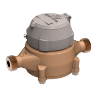
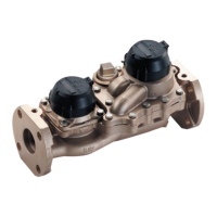
Details the design features, components, and operation of Recordall Turbo Series meters, including sizes and materials.
Discusses compatibility with AMR/AMI systems and the use of strainers for flow conditioning and protection.
Lists supporting documents like Product Data Sheet and Parts List for detailed information.
Covers important factors before installation, including piping arrangements, flow rates, strainers, and bypass systems.
Step-by-step guide on measuring, gap length, orientation, flange connections, and supporting the meter.
Outlines checks for leaks, proper operation, air purging, and flow rate verification post-installation.
Lists the standard tools recommended for servicing and maintaining the meters.
Explains the purpose of preventive maintenance: detecting and correcting defects for efficient operation and long life.
Details visual inspection for wear and tear, and verifying proper operation and pressure/flow rate.
Instructions for cleaning the meter exterior and internal components, including integral strainer units.
Recommends flushing components before extended shutdown or removal from service to prevent deposits.
Covers factory testing and procedures for recalibrating meters using integral calibration mechanisms.
Provides detailed steps and cautions for performing accuracy tests using test tanks or calibrated meters.
Explains how to adjust the calibration ring via the calibration shaft for accuracy adjustments.
Details the procedure for removing the meter head assembly, including safety warnings and pressure relief.
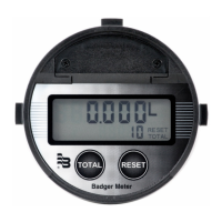
Explains how to remove the register lid, shroud, and assembly for in-line service.
Steps to remove the measuring element from the cover, including cage set screws and bayonet alignment.
Procedure for removing the magnet carrier from the measuring element insert and checking for wear.
Instructions for removing the upstream nose cone assembly to access the rotor and calibration ring.
Details the steps to remove the rear nose cone, including transmission shaft and protection tube.
Steps to disassemble the calibration ring assembly, including seal plug, lock screw, and thrust washer.
Guides on aligning the calibration ring, linkage, and nose cone assembly for proper function.
Instructions for inspecting the rotor worm, blades, and bearing bushings for damage or wear.
Steps for reassembling the rotor, nose cone assembly, and verifying free rotation.
Guidance on using new O-rings, cleaning surfaces, and tightening head bolts in a specific pattern.
Steps to close drain valves, purge air from the service line, and open valves to return meter to operation.
Provides detailed specifications including model, flanges, operating ranges, flow rates, pressure loss, and materials.
Presents specifications for larger meter sizes, covering model, flanges, operating ranges, flow rates, and materials.
| Brand | Badger Meter |
|---|---|
| Model | Recordall Turbo Series |
| Category | Measuring Instruments |
| Language | English |