CALIBRATION
LINKAGE
ARROW TIP
CAGE
INSERT
NOSE
CONE
TOP SIDE
SMALL HOLE WITH
CHAMFER UP
LARGE HOLE WITH
CHAMFER DOWN
INTO CAGE
THIS END
CALIBRATION RING
PIN
1-1/2", 2", 3" and 4" meters
RETAINING RING
TRANSMISSION
GEAR
CALIBRATION DRIVE
PLATE
CAGE INSERT
(TOP VIEW)
PIN OF
CALIBRATION
RING
6" meters
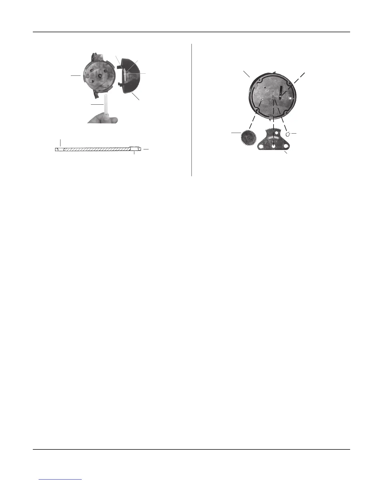
Figure 5: Calibration ring/linkage assemblies
Reassembling the Calibration Mechanism
1. Align the pin on the perimeter of the calibration ring with the arrow tip on the nose cone assembly (see Figure 5).
2. For 1-1/2", 2", 3" and 4" sizes, install the calibration linkage into the cage with the larger hole to engage the calibration
ring tab, with the side of chamfered edge of the hole towards the nose cone assembly (see Figure 5).
3. With the calibration linkage fully inserted to the cage stop, install the nose cone onto the cage and rotate it counter-
clockwise to engage the pin of the ring to the calibration linkage. The hole of the calibration linkage has to be aligned
onto the calibration shaft, engaging it fully so that the calibration ring cannot vibrate during operation.
4. Tighten the calibration shaft lock screw to securely hold the calibration ring in position.
After servicing or replacing the calibration mechanism, check the accuracy and calibration according to the instructions in
"Calibration Check and Adjustment" on page 10.
Inspecting the Rotor and Bearings
To inspect the rotor, remove the nose cone assembly from the measuring element insert as described in "Removing the
Straightening Vanes/Nose Cone" on page 13.
Check the rotor worm and blades for signs of damage and wear. Also inspect the bearing bushings in the front and rear shaft.
If damage or wear has occurred, replace the part (see Figure 6). If water deposits are found, remove any mineral deposits from
the rotor blade surfaces, cage insert interior disc, and nose cone vanes and mating surfaces.
Inspect the rotor bearing pins in the straightening vane and nose cone assembly for signs of damage and wear (see Figure 6).
The spherical end of the bearing pin must not show any drag lines and/or wear.
Servicing Parts and Assemblies
RTS-UM-00380-EN-09 Page 15 January 2015

 Loading...