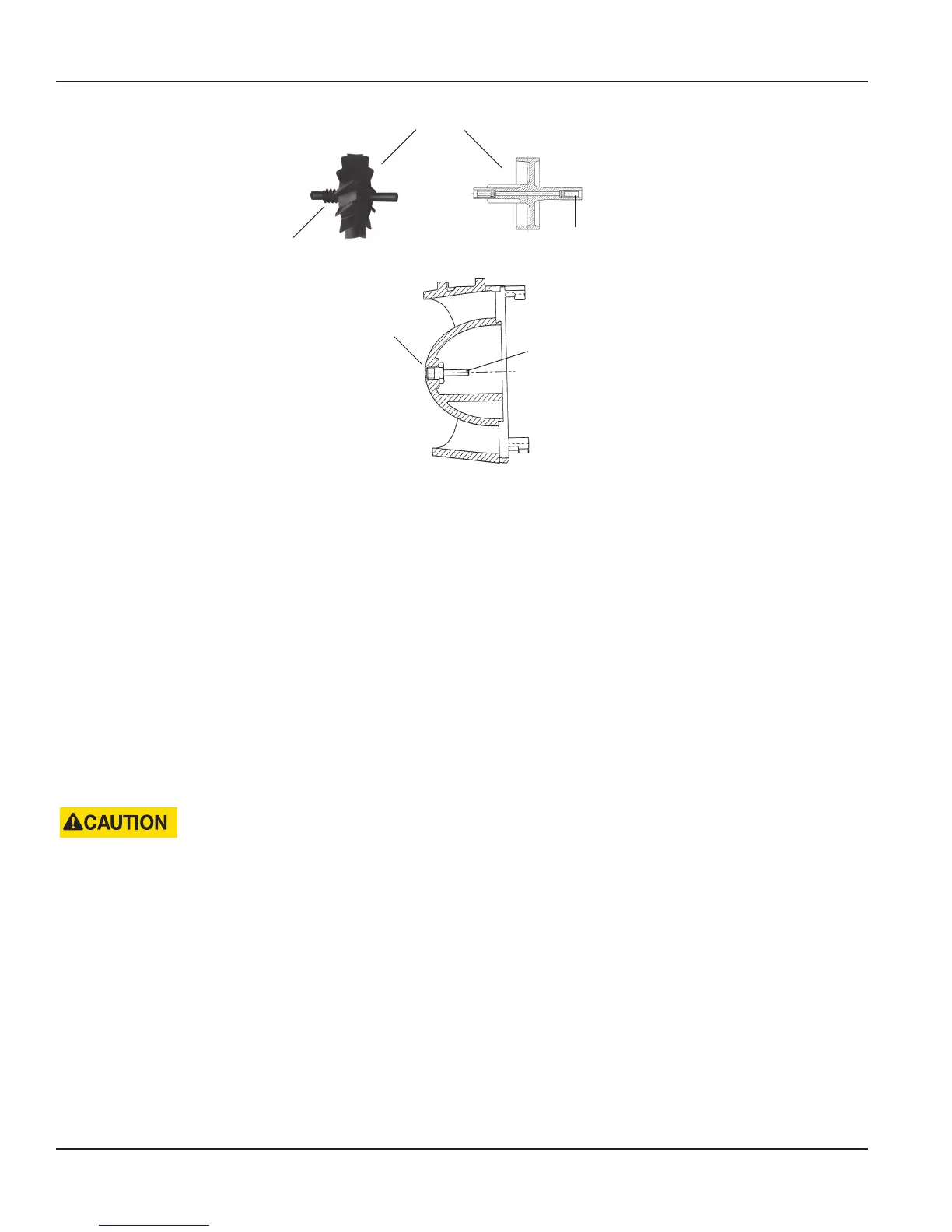
ROTOR
ROTOR
WORM
BEARINGS (2)
NOSE CONE
ASSEMBLY
(2)
BEARING
PIN
Figure 6: Rotor and nose cone assembly (1-1/2", 2", 3", 4" and 6" turbo head assemblies)
OTE:N Only highly-polished bearing pin ends provide a minimum of friction and optimal meter performance. Bearing
pins are an integral part of the straightening vane and nose cone assembly. Wear or damage would require the
replacement of this component.
Reassembling the Rotor and Bearings
1. Install the rear nose cone to the cage. See "Removing the Magnet Carrier" on page 13.
2. Place the rotor assembly with the worm gear side leading through the cage.
3. Place the rotor assembly on the rear rotor bearing pin, while tipping the assembly back so that the opening is up. See
“Removing the Calibration Mechanism” on page 14 for instructions on assembling the calibration rings with the nose
cone assembly.
4. Insert the front nose cone assembly partially onto the cage insert, engaging the bearing pin with the front bearing of
the rotor.
5. Tilt the measuring element insert assembly forth and back to verify that the rotor now engages the bearing pins on the
straightening vane/nose cones and is free to rotate and slide.
DO NOT FORCE THE NOSE CONE ASSEMBLY INTO THE CAGE INSERT. BE SURE THAT THE ROTOR ENGAGES BOTH THE
FRONT AND REAR ROTOR BEARING PINS PRIOR TO PRESSING THE NOSE CONE ASSEMBLY FULLY INTO THE CAGE
INSERT.
6. Press the nose cone assembly fully into the cage insert and turn it counter-clockwise, catching the calibration linkage
in the slot.
7. Verify that the rotor spins freely. If it does not, remove the nose cone assembly and repeat the procedure.
8. Install and tighten the nose cone assembly setscrew.
9. Holding the cover plate in one hand, align the thermoplastic cage bayonet-like tabs with the slots in the cover plate
(1-1/2" to 4" only).
10. Rotate the element clockwise until the cage setscrew hole is aligned. Install and tighten the cage setscrews (quantity of
1-1/2" to 4" meters, a quantity 4 for the 6" meter).
Servicing Parts and Assemblies
RTS-UM-00380-EN-09Page 16 January 2015
 Loading...