EasyManua.ls Logo

Badger Meter 2100 - User Manual

Badger Meter 2100
34 pages
To Next Page IconTo Next Page
Loading...
SCOPE OF MANUAL
Keep the manual in a readily accessible location for
future reference.
Changes and additions to the original edition of this
manual will be covered by a "CHANGE NOTICE"
supplied with the manual. The change notice will identify
the sections in this manual where the changes have
occurred.
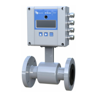
This manual contains information concerning the
installation, operation and maintenance of the Model
2100 flowmeter. To ensure proper performance of the
meter, the instructions given in this manual should be
thoroughly understood and followed.
Model 2100
TABLE OF CONTENTS
Page Page
Unpacking and Inspection................................. 1-1 OPERATION
General Specifications ...................................... 1-2 General Description .......................................... 3-1
System Diagram................................................ 1-3 Status Mode....................................................... 3-2
-- INSTALLATION PROCEDURE ............. Calibration Mode .............................................. 3-3
Enclosure Mounting.......................................... 2-1 Option Screens.................................................. 3-8
Wiring Connections .......................................... 2-2 Hexadecimal Conversions................................. 3-10
Sensor Mounting............................................... 2-4 Illustrated Parts List .......................................... 4-1
To avoid damage in transit, Badger products are
shipped to the customer in special shipping containers.
Upon receipt of the product, perform the following
unpacking and inspection procedures:
NOTE: If damage to the shipping container is
evident upon receipt, request the carrier to be present
when the product is unpacked.
a. Carefully open the shipping container following
any instructions that may be marked o the box. Remove
all cushioning material surrounding the product and
carefully lift the product from the container.
UNPACKING
&
INSPECTION
Retain the container and all packing material for
possible use in reshipment or storage.
b. Visually inspect the product and applicable
accessories for any physical damage such as scratches,
loose or broken parts, or any other sign of damage that
may have occurred during shipment.
NOTE: If damage is found, request an inspection by
the carrier's agent within 48 hours of delivery and file
a claim with the carrier. A claim for equipment
damage in transit is the sole responsibility of the
customer.
941164
4/98
1-1
Question and Answer IconNeed help?

Do you have a question about the Badger Meter 2100 and is the answer not in the manual?

Badger Meter 2100 Specifications

General IconGeneral
BrandBadger Meter
Model2100
CategoryMeasuring Instruments
LanguageEnglish

Summary

Scope of Manual

Unpacking and Inspection

Shipping Container Handling

Carefully open the shipping container following any instructions marked on the box.

Product Visual Inspection

Visually inspect the product and applicable accessories for any physical damage.

General Specifications

System Diagram

Installation

Electronic Enclosure Mounting

Details on selecting a location and mounting the electronic enclosure for operation and service.

Wiring Connections

Sensor Installation

Sensor General Description

Description of the FB-1 sensor, its PVC housing, epoxy resin, and mounting nipple.

Sensor Mounting Procedures

Instructions for installing the sensor to ensure accuracy, including Vcal and H dimensions.

Parshall Flume Installation

Manhole Flume Installation

Open Flow Nozzle Installation

Palmer-Bowlus Flume Installation

Weir Installation Procedures

Rectangular Weir Installation

Details for installing rectangular weirs with end contractions, including H and Vcal dimensions.

V-Notch Weir Installation

Details for installing V-notch weirs, including H and Vcal dimensions.

Leopold Lagco Flume Installation

Sensor Cable and Enclosure Connections

Sensor Cable Preparation

Step-by-step procedure for preparing sensor cable ends for connection to the electronics.

Enclosure Reassembly

Procedures for reconnecting internal cables and securing the front housing to the back housing.

Operation

Model 2100 Overview

Overview of the ultrasonic level transmitter's features, display, and keypad functions.

Status Mode Overview

Displays alarms, fluid level, distance, signal strength, and temperature for monitoring.

Alarms and Relays Status

Indicates tripped alarms (ECHO, 4-20, EEPRM, OVRR) and activated relays.

Self-Test Diagnostics

Performs diagnostic tests on EEPROM, sensor transmission (TX), and sensor echo.

Level Simulation Test

Allows simulation of fluid level/flow to test 4-20mA output and set points.

Calibration Mode

Security ID and Unit Selection

Setting the security ID and choosing measurement units (Feet, Inches, Meters, Millimeters).

Fullscale Headrise and Sensor Offset Settings

Adjusting maximum headrise and sensor offset values for accurate flow measurement.

Output Damping and Lost Echo Configuration

Configuring output signal response time and default behavior during signal loss.

Display Options and Flow Labeling

Selecting display mode (Flow/Level) and flow rate units and labels.

Element Configuration and Totalizer Setup

Setting element capacity, headrise, function, totalizer, and multiplier.

Set Point, Relay, and 4-20 mA Calibration

Configuring alarms, assigning relays, and calibrating the 4-20mA output.

Distance Calibration and Security ID Update

Calibrating distance readings and updating the user's security ID.

Optional Programming Screens

Special H;Q Curve Programming

Inputting custom height vs. flow curves using hexadecimal values for primary elements.

Custom Flow Rate Units and Totalizer Setup

Defining custom totalizer units, multipliers, and time base words.

Decimal to Hexadecimal Conversion

Hexadecimal to Decimal Conversion

Illustrated Parts List

Warranty Information

Nuclear Disclaimer

Related product manuals