September 2012 Page 17
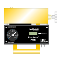
PFM Portable Hydraulic Testers PFM6, PFM6BD, and PFM8
1. Put one control valve in an operating position. (Only one control valve should be in an operating position at any one time.)
2. Slowly close the tester loading valve to achieve the pressure obtained in Step 3 under Pump Test or Step 1.c. under “Tee” Test and
record the ow. Repeat for all operating positions of all control valves.
a. If all components are in good operating condition, pressure and flow measurements should be the same as in Step 3 of the
Pump Test.
b. If a decrease in flow in any control valve position is noted, leakage is indicated. See Step 3 below for the test routine to
determine which control valve is at fault.
c. If the decrease in flow is the same with the control valve(s) in all positions, it indicates that the relief valve is at fault. (Note:
This can also indicate some other leak is present in the control valve such as a defective casting, damaged seals, or worn
valve position detents - but always check the relief valve FIRST.)
3. To locate the fault in the control valve, cylinder or motor, disconnect cylinder and plug connection.
a. Place the control valve handle in the position where greatest decrease of flow was noted.
b. Close the tester loading valve to achieve the test pressure and record the flow.
c. If the same decrease in flow is noted as in test performed in Step 2.b. above, then the control valve is at fault. HOWEVER, if the
flow readings are now higher and comparable to the other control valves, then a faulty cylinder or motor is indicated.
Relief Valve in Separate Housing
1. 1. Install the tester in a “Tee” Test conguration to the line connecting the pump and relief valve. Plug any extra outlets.
2. Close the tester loading valve and watch the pressure and ow.
a. Reconnect the control valve to the tee. Put a control valve into a power output mode with the output flow blocked, such as a
cylinder at the end of its stroke.
b. Close the tester loading valve while watching the pressure. Pressure will increase until the relief valve opens. Record the
pressure at this point. Repeat to check the relief valve adjustment.
Relief Valves
Often relief valves will start to open before they reach their full pressure flow settings. This can be noted by comparing the
pressure and flow rate readings made in Step 3 under “Tee” Test. Any great decrease in flow rate from tests made in Step 3
under “Tee” Test indicates a faulty relief valve.
 Loading...