September 2012 Page 9
PFM Portable Hydraulic Testers PFM6, PFM6BD, and PFM8
CAUTION
Caution - Read instructions thoroughly before installing the tester. If you have any questions regarding product
installation or maintenance, call your local supplier or the factory for more information.
INSTALLATION
CAUTION
Caution - The information in this manual is for general application only. Any guidelines furnished by the manufactur-
er of the machine’s hydraulic components should be followed. Specific systems may require specific test procedures.
Install the PFM6, PFM6BD or PFM8 tester at any location in the hydraulic circuit with the flow from “IN” to “OUT” as marked
near the ports of the flow meter. The “IN” and “OUT” ports on the PFM6BD indicate the primary flow direction. It is advisable to
keep any elbows, tees, valves, etc. at least 12 inches (31 cm) away from the inlet and outlet ports to preserve the accuracy of
the flow measurement. Use quick disconnect couplings for easy connections and to keep tester sealed and clean when not in
use.
Diagrams illustrating typical test placements for the testers are located in the Test Procedures section.
OPERATION
WARNING
Warning - All testers are shipped with the loading valve in the closed position. The loading valve must be opened
fully before initiating flow and testing of the hydraulic circuit. Turn the loading valve handle counterclockwise to the
fully open position. Failure to open the loading valve fully can result in injury to personnel and/or damage to the
equipment.
The PFM6 and PFM6BD testers utilize a 3 position, single toggle switch to turn on the power and to select to display either
flow or temperature readings. These models are factory calibrated for either U.S. or metric readings.
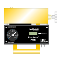
The PFM8 testers can be changed in the field between U.S. and metric readings via a slide switch located in the center of the
front panel. Use a small pointed object to slide this switch to the desired position. See Figure 3.
After the selecting U.S. or metric, power and display options are made via the membrane switches. When the “ON” switch is
pressed, pressure will show in the left display and flow in the right display. To view temperature in the right LCD, simply press
the “TEMP.” switch. To view Power in the left LCD, press the “PWR.” switch.
 Loading...