Do you have a question about the Badger Meter Flo-tech PFM Series and is the answer not in the manual?
Details features of the PFM6 digital hydraulic tester, including accuracy, display, and components.
Outlines the features of the PFM6BD bi-directional tester, focusing on testing capabilities.
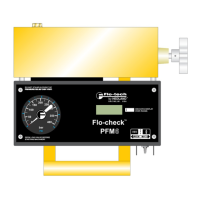
Lists features of the PFM8 model, highlighting its dynamometer capabilities and display options.
Details the materials used for various components of the PFM testers.
Lists key performance metrics like flow accuracy, pressure rating, and temperature ranges.
Explains the standard calibration process and traceability for the testers.
Describes the structure and meaning of different model numbers for PFM testers.
Provides a visual diagram showing the physical dimensions of the testers.
Lists the physical dimensions and weight for different PFM models.
Provides caution advice for installing the hydraulic testers and recommended practices.
Explains the critical warning regarding the loading valve operation and its importance.
Describes how to use the toggle switch and membrane switches for operation and display selection.
Tips for prolonging battery life and automatic power-off features for testers.
Reiterates the critical warning about opening the loading valve before use to prevent injury.
Specific caution for PFM6BD models regarding high-pressure deadhead applications.
Differentiates loading valve types between PFM6/PFM8 and PFM6BD models.
Explains the slide and membrane switches for the PFM8 model's operation.
Notes the impact of cold temperatures on battery voltage and low battery indicators.
Overview of what the PFM testers measure and general steps for test preparation.
Outlines the general steps and conditions required before performing tests on the system.
Describes the required tee installation for the pump test and initial setup.
Step-by-step instructions for conducting a pump test and interpreting results.
Details the installation requirements for the "Tee" test setup.
Explains how the "Tee" test is used to isolate and test pumps and relief valves.
How to interpret flow readings for pump condition and potential suction issues.
Procedure for testing relief valves located in separate housings.
Illustrates the hydraulic circuit setup for testing control valves, cylinders, and motors.
Steps to identify faults in control valves, cylinders, or motors based on flow readings.
Methods for testing relief valves, both in separate housings and general.
Steps to take if the load valve fails to load the system.
Addresses issues when no flow reading is indicated, suggesting turbine blockage.
Explains the function of burst discs and when they need replacement.
Caution regarding over-torquing the burst disc housing to prevent premature rupture.
Detailed steps for replacing burst discs in PFM6 and PFM8 testers.
Specific procedure for replacing burst discs in the PFM6BD model.
Specifies the correct torque for the PFM6BD burst disc housing.
Describes how low battery conditions are indicated on different PFM models.
Step-by-step guide on how to replace the AA batteries in the testers.
Displays charts showing pressure drop against flow rate for PFM6 and PFM8 models.
Presents charts for PFM6BD models, including forward and reverse flow data.
Lists formulas related to calculating flow rate and related parameters.
Provides formulas for calculating horsepower (HP) and kilowatts (kW).
A table for converting fluid viscosity between SUS, ISO-VG, Centistoke, and Centipoise.
Instructions on how to obtain and process a Returned Goods Authorization (RGA).
Information regarding the disposal of electronic equipment according to the WEEE directive.
Specifies that the warranty applies to the Flo-tech Portable Hydraulic Testers.
Details the 12-month warranty period for defects in materials and workmanship.
Outlines the procedure for returning products for warranty claims.
Defines the limitations and exclusions of the product warranty.
Disclaims consequential damages and other liabilities beyond the warranty terms.
| Brand | Badger Meter |
|---|---|
| Model | Flo-tech PFM Series |
| Category | Test Equipment |
| Language | English |