Installing the Encoder
INSTALLING THE ENCODER
Bayonet Mount
The fully potted assembly has a bayonet mount compatible with all Recordall Disc, Turbo Series, Compound Series, Combo
Series and Fire Series meters and assemblies.
The bayonet mount positions the encoder in any of four orientations for visual reading convenience. The device can be
removed from the meter without disrupting water service.
The device is permanently sealed to eliminate the intrusion of moisture, dirt or other contaminants, and is suitable for
installation in all environments, including meter pits subject to continuous submergence.
Install the device on the water meter and secure it using the tamper-proof screw provided.
Wire Connections
The following connection options are available. For more information on in-line connectors, refer to the document, ORION
Water Endpoints Installation Manual, available at www.badgermeter.com.
HR-E LCD
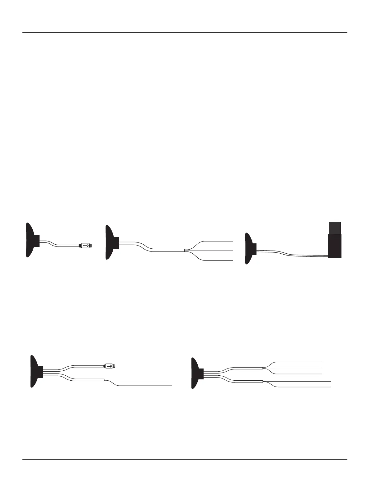
The HR-E LCD encoder has a single cable, available with three different wiring options. Refer to Figure 2.
• In-line connector
• Flying lead for field splice connection
• Prewired to an AMR/AMI endpoint
Encoder Cable with In-line Connector
Flying Lead
RED - Power
GREEN - Data
BLACK - Ground
Prewired to AMR/AMI Endpoint
Figure 2: HR-E LCD wiring options
HR-E LCD 4-20
The HR-E LCD 4-20 encoder is available with dual output wire connections. Refer to Figure 3.
Encoder side cable
• In-line connector
• Flying lead for field splice connection
4-20 side cable
• Flying lead for field splice connection
4-20 mA Cable
RED - Loop/External Power +
BLACK - Loop Return/External Power –
Encoder Cable with In-line Connector
4-20 mA Cable
RED - Power
GREEN - Data
BLACK - Ground
Encoder Cable with Flying Lead
RED - Loop/External Power +
BLACK - Loop Return/External Power –
Figure 3: HR-E LCD 4-20 wiring options
Page 6 April 2019LCD-UM-01482-EN-07