11
DISPLAY MANUAL DP C01.UART
to 3, the actual levels include Levels 0/1/2/3.
After setting the parameters, the instrument
has to be turned off and then restarted to
make the settings effective.
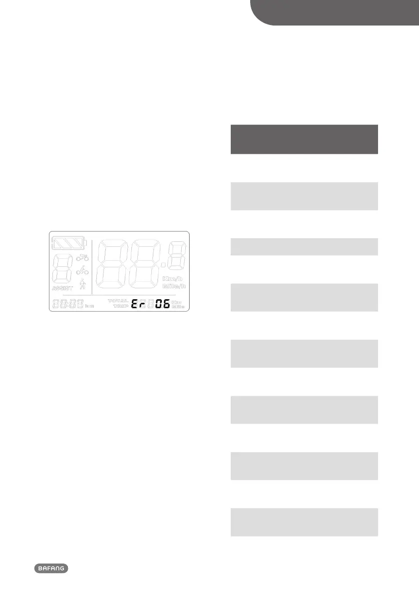
• Error code indication
When any fault occurs to the electric bicy-
cle’s electrical control system, the instrument
will automatically indicate an error code, of
which the meaning is defined in the follow-
ing table. The error code indication interface
is shown in the following figure:
• Indication of battery communication
information
Information
code
Definition Unit
P1
Charge and dis-
charge times
P2
Full charge
capacity (FCC)
mAh
P3
Remaining
capacity (RC)
mAh
P4 Total voltage mV
P5
Longest period
without charge
H
P6
Battery tem-
perature
°C
P7.1
Voltage of
cell 1
V
P7.2
Voltage of
cell 2
V
... ...
P7.C
Voltage of cell
12
V
P8 Average current A
P9
Absolute state
of charge
P10
Relative state of
charge
P11
Period since last
charge
H
PARAMETER SETTING