Do you have a question about the Baker SterilGARD SG604-INT and is the answer not in the manual?
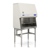
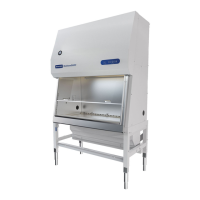
Details cabinet physical dimensions including footprint, height, and shipping.
Lists the weight of the cabinets in various configurations.
Describes the connections and pressure ratings for laboratory utilities.
Specifies power requirements, circuit protection, and outlet details.
Provides airflow data for different vent-to-room and canopy exhaust connections.
Details static pressure requirements for exhaust duct connections.
Lists the recommended operating conditions for cabinet use.
Explains common symbols and terminology used in the manual.
Steps for unpacking and initial inspection of the cabinet upon arrival.
Instructions for preparing the cabinet and adhering to regulatory requirements.
Guidance on selecting an optimal location to ensure proper airflow.
Requirements for cabinets exhausting air directly into the laboratory space.
Guidelines for connecting the cabinet to an external exhaust system.
Procedures for making final connections and performing initial operational tests.
Overview of procedures to validate cabinet performance according to specifications.
Methods and tools required for verifying cabinet airflow performance.
Detailed steps for scanning HEPA filters to detect leaks.
Method for visualizing airflow patterns within the cabinet using smoke.
Tests to confirm proper installation and functionality of alarms.
Detailed steps and warnings for replacing HEPA filters.
Procedure for removing and installing the exhaust HEPA filter.
Procedure for removing and installing the supply HEPA filter.
Steps for safely removing the cabinet's view screen.
Instructions for replacing the fluorescent lamp in the cabinet.
Guide for replacing the UV germicidal lamp.
Procedure for replacing the cabinet's touchpad interface.
Information on the optional pressure monitor and its programming.
List of electrical and mechanical replacement parts with part numbers.
Electrical wiring diagrams for understanding cabinet circuitry.
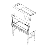
Diagrams showing the physical layout of electrical components.
Diagrams illustrating various cabinet wiring configurations.
Wiring instructions for the auxiliary blower switch status option.
Wiring instructions for the auxiliary cabinet monitoring option.
Wiring details for the FlexAIR canopy exhaust connection.
Flowchart for diagnosing issues when the motor/blower will not start.
Second part of the flowchart for motor/blower start issues.
Flowchart for diagnosing issues when cabinet outlets are not working.
Second part of the flowchart for cabinet outlet issues.
Flowchart for diagnosing issues when fluorescent lamps do not work.
Second part of the flowchart for fluorescent light issues.
Flowchart for diagnosing issues when ultraviolet lights do not work.
Second part of the flowchart for UV light issues.
Flowchart for diagnosing issues when the FlexAIR system is alarming.
Second part of the flowchart for FlexAIR alarming issues.
| Motor | ECM (Electronically Commutated Motor) |
|---|---|
| UV Light | Optional |
| Certifications | NSF/ANSI 49 |
| Construction | Stainless steel interior with powder-coated exterior |
| Type | Class II Biological Safety Cabinet |
| Noise Level | ≤63 dBA |
 Loading...