EasyManua.ls Logo

Baker BDINQ400 User Manual

Default Icon
15 pages
To Next Page IconTo Next Page
Page #1 background imageLoading...
Page #1 background image
P. O. Drawer E / 161 Gatehouse Road / Sanford, Maine 04073 / USA
800-992-2537 / 207-324-8773 / Fax: 207-324-3869 / bakerco@bakerco.com
398D003 Rev B i
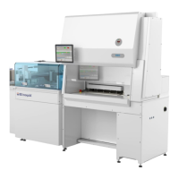
INSTALLATION MANUAL
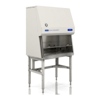
Biological Containment Cabinet
BD InoqulA
MODEL
BDINQ400
Revision
Date
Description
A
06/26/14
Initial release
B
07/28/14
Revised and updated instructions
C
08/18/14
Revised and updated instructions page 4
Question and Answer IconNeed help?

Do you have a question about the Baker BDINQ400 and is the answer not in the manual?

Baker BDINQ400 Specifications

General IconGeneral
BrandBaker
ModelBDINQ400
CategoryLaboratory Equipment
LanguageEnglish

Summary

Preparing the SA Module and Cabinet for Installation

Step 1: Removing Side Covers and Panels

Remove right side duct cover and lower SA module panels for access to mounting holes.

Lifting and Placement of the BDINQ400

Step 1: Verify Lifting Hoist Ring Attachment

Ensure all four lifting hoist rings are properly attached to the top of the cabinet.

Step 2: Utilize Spreader Beam for Unbalanced Loads

Use a spreader beam with adjustability for unbalanced loads, considering cabinet weight.

Step 3: Attach Lifting Equipment and Balance

Attach lifting equipment, lift slightly to verify balance, and adjust for even balance.

Step 4: Position and Lower Cabinet onto Chassis

Position cabinet over SA chassis, carefully lower, aligning rear flange and mounting studs.

Manual Lifting of the BDINQ400

Attaching Lifting Aids to the Cabinet

Step 3: Lift Cabinet to Table Top Height

Lift cabinet onto a lift table raised to table top height for positioning.

Attachment of the BDINQ400

Step 1: Secure Cabinet to Left Side

Insert two M6 x 30 mounting screws on the left side from underneath the SA chassis table top.

Step 2: Secure Cabinet to Right Side

Insert three M6 x 30 mounting screws in the slots located in the right side plenum.

Step 3: Attach Rear Wall to Shifter Module

Attach all M6 mounting hardware for cabinet rear wall to shifter module and tighten.

Related product manuals