ag
Maximum
240 120
120 120 240 120
No connection at Terminal Lug #2.
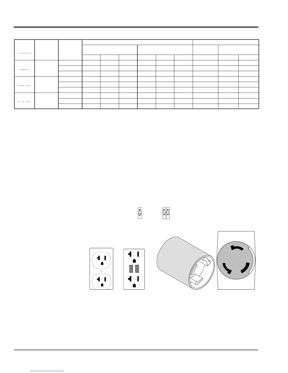
Receptacle Panel Load Connections, see Figure 4-4.
1. 240/120VAC voltage is present at the receptacle panel at all times when generator is
running.
2. Carefully inspect all Individual load cables for broken insulation or other signs of
damage. Never use a damaged cable. Replace it before usage.
3. Individual load cables may be routed into the receptacle compartment through the
Enclosure Electrical Access Panel.
4. Individual load cables may be connected or disconnected while generator is running.
Use extreme care not to touch any electrical wire or terminal to avoid shock hazard.
5. Keep Enclosure Electrical Access Panel closed at all times. This prevents rain or other
harmful elements from entering the compartment. Output metering and gauges can be
observed through the window in the Enclosure Electrical Access Panel.
Figure 4-4 Receptacle Panel (Single Phase)
Note:
Single phase power is
always available.
(GOLD)
X
(GOLD)
Y
G
W
(SILVER)
CS6369
125/250V
50A
X
Y
W
Test
Reset
CS6365N
GFI Outlet
120V, 20A
STD Outlet
120V, 20A
240V, 50A
Circuit Breakers (Single or Double pole)
Circuit Breakers provides protection on some
units. To reset a breaker, place it in the OFF
then the ON position.