INSTALLATION
11 QF-T06-Rev 3 2017-02-28
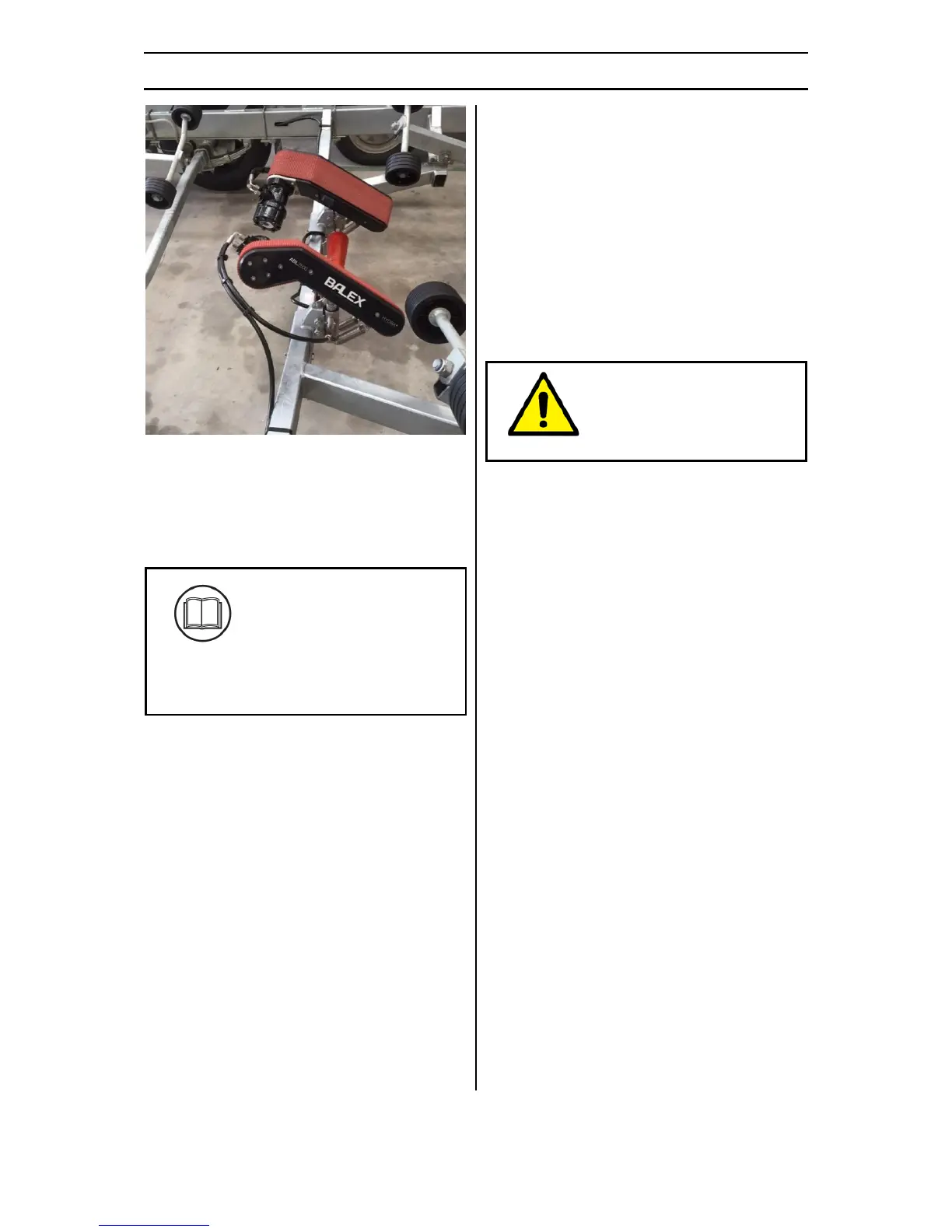
Figure 7 - Drive Hose Layout
XI. Tidy and secure all the hoses with the
cable ties provided in the Hydraulic Hose
Kit (13) and cut the cable ties short.
XVI. Review the Accreditation Pack for any
additional modifications.
Please refer to the
Accreditation Pack to
determine if there are any
other specific modifications to
your boat and trailer
combination.
Stage 5 - Testing
I. Ensure the hydraulic hose fittings on the
Drive Units (1,2) are fully tightened.
II. Remove the lid from the Power Unit –
Pump Assembly (7) and ensure the hose
fittings are fully tightened.
III. Fill the oil tank in the Power Unit – Pump
(7) to level indicated.
IV. Ensure the bolts holding the Power Unit
– Pump Assembly (7) to the Mounting
Bracket (8) are fully tightened to 19Nm
using the torque wrench.
V. Remove the lid from the Power Unit –
Battery Assembly (9) and ensure the
power cables are fully tightened to the
Battery (11).
VI. Fit the lids onto the Power Unit – Pump
(7) and the Power Unit – Battery (9), then
using the Mounting Bracket Straps fasten
accordingly (8,10).
VII. Ensure the bolts holding the Drive Unit
Brackets (3) to the trailer cross beam are
fully tightened to 35Nm using the torque
wrench.
VIII. Ensure the bolts holding the Drive Unit
Brackets (3) to the Drive Units (1,2) are
fully tightened to 88Nm using the torque
wrench.
IX. Ensure the bolts holding the Rear Rollers
(4) to the cross beam are fully tightened.
Caution:
The Drive Units (1,2) will lift
25mm and their belts will
start turning with the next
steps.
X. Push the isolator key into the Power Unit
– Pump (7), and turn the system on. Hint:
The lights should flash and the battery
level indicator will stay on. A green light
on the right side of the panel indicates
the battery is fully charged.
XI. Use the Launch button on the Power Unit
– Pump (7) and operate the ABL2500® for
20 seconds ensuring the Drive Unit belts
are rotating in the correct direction. Hint:
The system is self-bleeding and will take
4-5 seconds to fill the hoses.
XII. Use the Retrieve button on the Power
Unit – Pump (7) and operate the
ABL2500® for 20 seconds ensuring the
Drive Unit belts are rotating in the
correct direction.
XIII. Now test the Remote Controls (12) are
working (one at a time) by pointing the
remote at the Power Unit – Pump (7) and
pressing the Retrieve and Launch buttons
for 5 seconds each and confirm the Drive
Unit belts are rotating. Hint: If the
remotes are not working see Appendix 5
to program the remotes, then repeat this
step.
XIV. Re-check all the hose fittings to ensure
there are no oil leaks either at the Drive
Units (1,2) or the Power Unit – Pump (7).
XV. Open up the Power Unit – Pump (7) and
fill the oil tank to the level indicated.