INSTALLATION
7 QF-T06-Rev 3 2017-02-28
Installation Stages
Installation of the ABL2500® includes six stages:
1. Boat Removal
2. Drive Unit Installation
3. Power Unit Installation
4. Hydraulic Hose Installation
5. Testing
6. Boat Loading and Final Adjustment
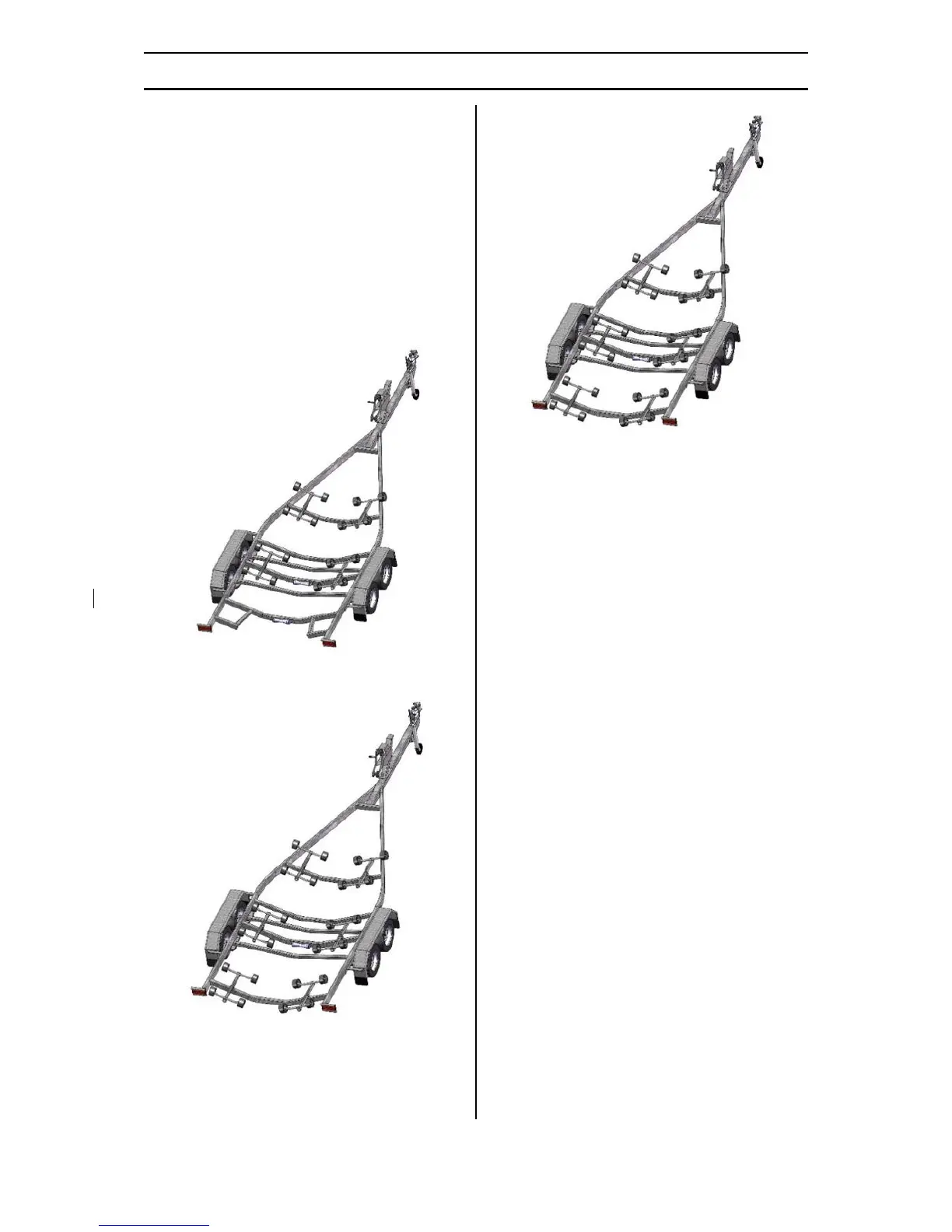
Further it should be noted that there are typically
three styles of trailer the ABL2500® system can fit
to:
Figure 1 – Cutaway Trailer Type.
Figure 2 – Fixed Beam Trailer Type.
Figure 3 – Drop-In Beam Trailer Type.
The following six installation steps are
compatible with any trailer type. However
additional trailer specific information can be
found in the assembly drawings found in
Appendix 1 (Cutaway Trailer), Appendix 2 (Fixed
Beam Trailer) and Appendix 3 (Drop-In Beam
Trailer).
Stage 1 - Boat Removal
I. Position the trailer and boat on a flat
surface, with the motor raised and
ensure there is at least 3m behind the
motor.
II. Position a tyre behind the transom (rear)
of the boat. Disconnect the safety
chain/latch and unwind the winch rope
0.5m while simultaneously pushing the
boat backwards off the trailer.
III. Slowly let out more winch rope while
simultaneously pushing the boat
backwards onto the tyre. Hint: You may
need to re-position the tyre during this
step.
IV. Drive the trailer forward then position
two tyres under each side of the boat
about 1-2m from the transom of the
boat. Hint: During this step you want the
boat to stay in position while the trailer is
driven forward.
V. Drive the trailer further forward so the
weight of the boat is on the rear rollers
only then position wooden blocks
centrally under the boat and forward of