INSTALLATION
8 QF-T06-Rev 3 2017-02-28
the tyres. Hint: The higher the blocks the
higher the boat which will allow it to load
easier back onto the trailer later.
VI. Drive the trailer forward slowly so the
weight is sitting only marginally on the
rear rollers then put some wooden
blocks under the side chines to restrict
any sideways movement of the boat.
VII. Remove the winch rope and drive
forward so the trailer is fully clear of the
boat.
VIII. You are now ready to start fitting the
ABL2500® to the trailer.
Stage 2 - Drive Unit Installation
I. Make sure all the items are on the boat
trailer before you start, i.e. spare wheels,
rollers, jockey wheel, winch handle etc.
II. Identify the rear cross member which the
drive units will be fitted to and mark the
centre point. Hint: Measure this point
from the outside main chassis in towards
the centre of the cross member using a
tape measure.
III. Now take the Drive Unit Brackets (3),
apply Grease on the underside of these
brackets and position onto the cross
member, do not bolt down just yet. Hint:
The angle of the brackets should be
facing inward.
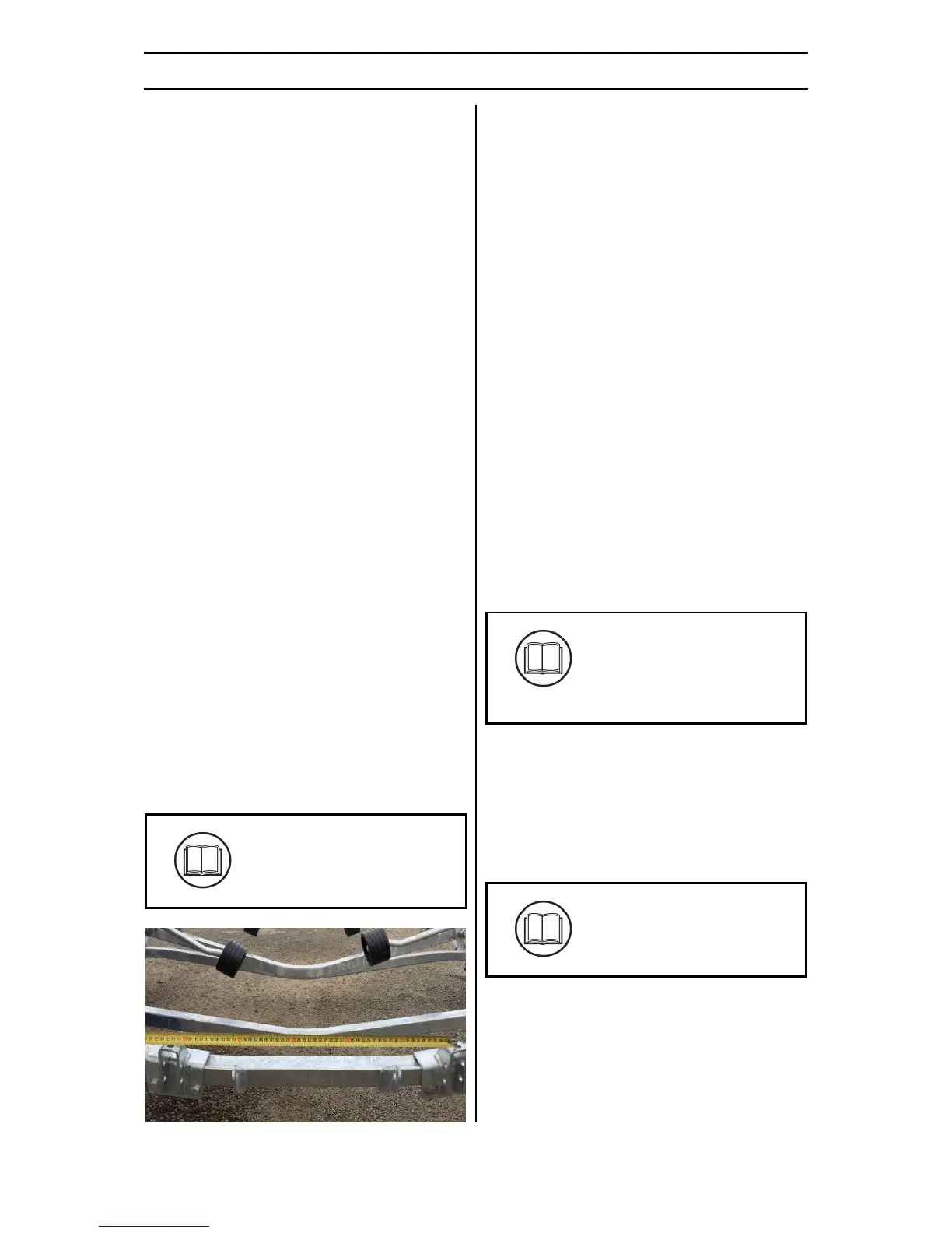
IV. Measure the centre to centre distance
using the centre of the holes on top of
the brackets. The centre to centre
distance should match that
recommended in the Accreditation Pack.
Figure 4 - Fitting the mounting brackets
V. Tighten the Drive Unit Brackets (3) to the
trailer.
VI. Position the Drive Unit - Starboard (1) to
the Drive Unit Bracket (3) installed in the
previous step. Fit two M12 Grade 8.8
bolts through the Drive Unit – Starboard
(1) and Drive Unit Bracket (3), only finger
tight. Hint: The bolt head shall be on the
outward side bracket, while the washer
on the threaded end of the bolt.
VII. Identify the adjuster bolt (M10 x 35),
apply Grease and thread it into the hole
underneath the Drive Unit (1) belt about
10mm.
VIII. The M12 bolts can now be tightened
between the Drive Unit Bracket (3) and
the Drive Unit (1).
IX. Repeat for the second Drive Unit – Port
(2).
X. Check the Accreditation Pack and
determine if the Rear Rollers and
Brackets need to be removed and
replaced. Fit the Rear Roller Kit (4) if
applicable. Only finger tight at this point.
XI. The centre to centre distance between
the roller brackets should match that
recommended in the Accreditation Pack.
Hint: Measure the distance by ensuring
the rollers are horizontal and from the
centre point of each roller.