Do you have a question about the Balluff BNI IOL-309-002-Z019 and is the answer not in the manual?
| Product Type | BNI IOL-309-002-Z019 |
|---|---|
| Communication Protocol | IO-Link |
| SIO Mode | Yes |
| Cycle Time Min. | 2.3 ms |
| IO-Link Port Type | A |
| Rated Operating Voltage Ue DC | 24 V DC |
| Protection Class | III |
| Protection Rating | IP67 |
| IO-Link Device Protocol | IO-Link V1.1 |
| Operating Voltage | 20-30 V DC |
| Switching Function | Normally Open |
| Operating Temperature | -25 to +70 °C |
| Ambient Temperature Ta | -25 to +70 °C |
| Storage Temperature | -40 to +85 °C |
| Housing Material | Plastic |
| Connection | M12 |
| Connection Type | M12 connector |
| Operating Voltage Ub | 18...30.2 VDC |
| Operating Current Ie | 100 mA |
Describes the Balluff IO-Link I/O module, also called a sensor/actuator hub.
Explains the manual's organization and structure.
Details formatting conventions for enumerations, actions, syntax, and cross-references.
Explains the meaning of symbols like 'Attention!' and 'Note'.
Lists common abbreviations used in the manual.
Notes that product images may differ from the actual product.
Defines the intended application of the BNI IOL module.
Provides safety instructions for installation and startup.
Covers obligations, authorized personnel, and malfunctions.
Warns about chemical resistance and material checks.
Safety warning about disconnecting power before maintenance.
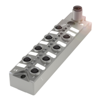
Provides a visual overview of the BNI IOL module's connections and ports.
Explains how to attach the BNI IOL modules using screws.
Details the functional ground and IO-Link connection via M12 connector.
Instructions for connecting the sensor hub and ground.
Lists available sensor hub variants.
Describes the standard input/output port M8.
Describes the extension port (M8, female).
Explains how to use the No. 7 slot as an extension port.
Details configuring the extension port using parameter 0x55.
Explains setting the serial number using parameter 0x54.
Provides IO-Link data details like transmission rate and cycle time.
Shows the bit mapping for input process data.
Shows the bit mapping for output process data.
Lists identification and parameter data with DPP, SPDU, index, etc.
Details the parameter for input inversion.
Explains the parameter for configuring input/output direction.
Describes the parameter for safe output states in case of faults.
Details parameters for voltage monitoring.
Details parameters for monitoring output status.
IO-Link data for the extended configuration.
Input data mapping for the extended configuration.
Output data mapping for the extended configuration.
Parameter data for the extended configuration.
Input inversion parameters for the extended configuration.
Input/Output configuration parameters for the extended configuration.
Safe state parameters for outputs in the extended configuration.
Voltage monitoring parameters for the extended configuration.
Output monitoring parameters for the extended configuration.
Setting serial number for the extended configuration.
Lists error codes and their descriptions.
Lists event codes and their descriptions for different IO-Link revisions.
Details compatibility with IO-Link versions.
Explains data storage functionality in IO-Link v1.1.
Describes the device's support for block configuration.
Explains how to restore factory settings.
Provides physical dimensions of the module.
Details housing material and weight.
Lists supply voltage, ripple, and current consumption.
Specifies ambient temperature, storage temperature, and degree of protection.
Explains module status LEDs (COM US/UA).
Explains LED indicators for input/output status.
Explains LED indicators for the extension port.
Explains the product type code structure.
Provides ordering codes for the product.