39
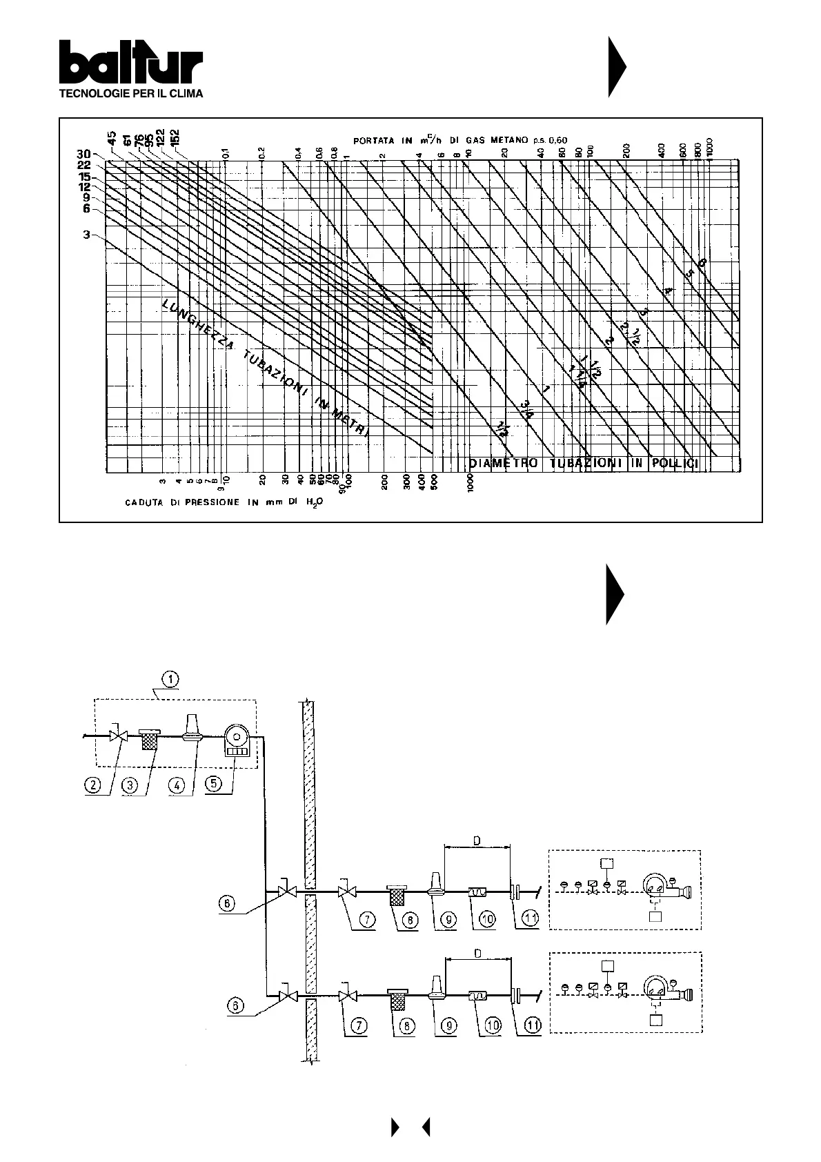
DIAMETER OF PIPES IN INCHES
PRESSURE DROP IN mm OF H
2
O
FLOW IN m
c
/h OF METHANE p.a. 0,60
LENGTH OF PIPES IN M
ETERS
DIAGRAM FOR CALCULATING THE DIAMETER OF THE
PIPES IN RELATION TO THEIR LENGTH AND GAS FLOW
N° BT 8058
DIAGRAM OF CONNECTING MORE THAN ONE BURNER TO
THE GAS PIPE NETWORK AT AVERAGE PRESSURE
N° BT 8530/1
1 - Measuring and reducing unit
2 - Interception
3 - Filter
4 - Reducer
5 - Meter
6 - Emergency interception (installed outside)
7 - Ball cock
8 - Filter
9 - Final reducer or stabilizer
10- Anti-vibration joint
11- A couple of flane
D = Distance between pressure stabilizer and valve about 1,5 ÷ 2 m
 Loading...