40
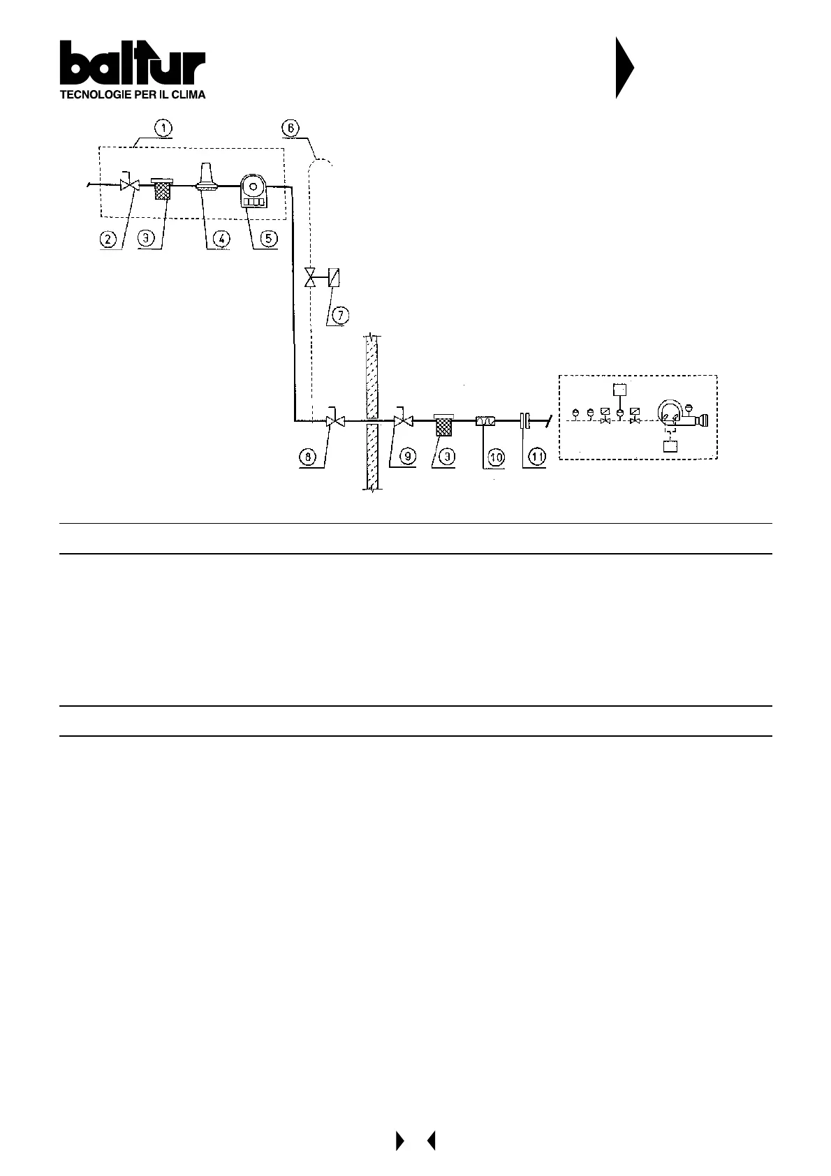
1 - Measuring and reducing unit
2 - Interception
3 - Filter
4 - Reducer
5 - Meter
6 - Wire gauze flame trap
7 - Eventual automatic overflow valve (it should obviously
unload outside in a suitable place)
8 - Emergency interception installed outside
9 - Ball cock
10- Anti-vibration joint
11- A couple of flange
DIAGRAM OF CONNECTING A BURNER TI THE
GAS PIPE NETWORK AT AVERAGE PRESSURE
N° BT 8531/1
ELECTRICAL CONNECTIONS
The three-phase or single-phase electric supply line of the minimum section, in proportion to the power absorbed by the
burner, must be equipped with a fuses switch.
Furthermore, regulations require a switch on the burner’s feed line which should be located outside the boiler room in an
easily accessible position.
All electric lines must be protected by flexible sheaths, be firmly secured and be laid a long way from high temperature
parts. For the electrical connections (line and thermostat) see the relevant diagram.
DESCRIPTION OF OPERATIONS
By closing the main switch, and if the thermostats are closed, voltage will reach the cyclic relay motor which will then
start operating. The fan motor is then turned on and it will carry out a pre-ventilation of the combustion chamber.
At the same time, the motor which controls the combustion air shutter moves the air shutter to the correct open position
for the 2nd flame.
Pre-ventilation of the combustion chamber takes place when the air shutter is open at the 2nd flame position. At the end
of the pre-ventilation phase, the combustion air shutter is taken back to the 1st flame position, ignition takes place and,
after three seconds, the principle and safety gas valves open and the burner starts up.
We should point out that:
a) the two-stage principle valve is fitted with a device which regulates gas delivery for the 1st
and 2nd flames (see specific instructions for the 2-stage valve model fitted to the burner).
b) The safety valve is an ON/OFF version (see specific instructions for valve model fitted to
the burner).
c) The combustion air can be regulated by hand by means of a proper gate (BT 8606 refers).
Keeping in mind that the burner is in ON/OFF execution, the position in which the air gate must be regulated is
the one necessary for the operation at the maximum delivery required.
Flame presence detected by its own relative control device, permits the continuation and completion of the ignition phase
with the disconnection of the ignition transformer.
Subsequently, the 2nd flame is inserted (there is an increase in combustion air and the principle valve is open at the 2nd
stage position).
In the case of flame failure, the control box activates a “safety shut down” within two seconds of the opening at the 1st
flame position of the principle valve. When there is a “safety shut down”, the valves are immediately re-closed.
To unblock the control box from the safety position, push the luminous button on the control panel.