Dimensions
Mounting
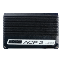
H5000 PILOT COMPUTER
INSTALLATION GUIDE
*988-10673-001*
Masthead Unit
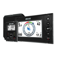
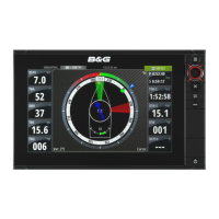
Graphic Display
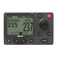
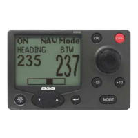
H5000 Pilot Controller
GPS Antenna
1
System wiring
2
3
4
Micro-C CAN bus backbone
H5000 Computer Unit
Speed sensor
Depth sensor
5
6
7
8
H5000 Pilot Computer
Rudder Feedback Unit
Compass
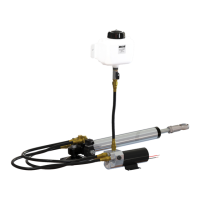
Hydraulic Ram
9
10
11
12
Terminator
12 Volts
1 x H5000 Pilot Computer
4 x Fixing screws, 3.5 * 19 mm
1 x Micro-C Drop cable (male)
1 x Micro-C T-Joiner
6 x Connectors
1 x 30 Amp fuse
1
2
3
4
5
6
Parts included
1
2
4
3
For product manuals, technical specificaƟons,
cerƟficates and declaraƟons,
refer to the product website on:
www.bandg.com
211.0 mm (8.31")
195.0 mm (7.68")
65.5 mm (2.58")
92.0 mm (3.62")
196.0 mm (7.72")
12V
1
T T
2
5
7 8
6
9
11
4
3
12V
12
10
PT
12V
T
12V
UP
5
6