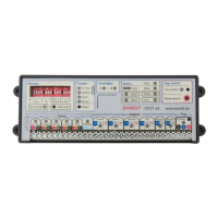
0 V
12 V
MCU output
Schematic of an output
Relay
12 V /
1 A
com
nc
no
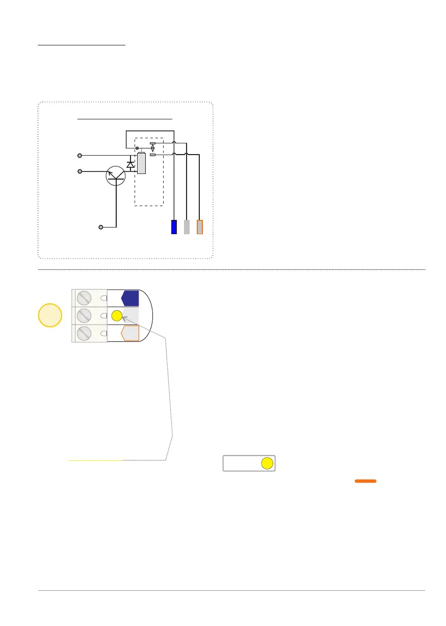
Via this three-output terminal connector the controller reports if the BANDIT is
switched into Monitoring mode [Guard] or not.
See also p. 5, Monitoring input.
Properties of the monitoring output [Guardout]
As long as the unit is in monitoring mode:
- Contacts COM and NO are closed (ie, COM and NC open).
- The yellow LED lights Guard.
- Yellow monitoring Status LED is on .
- The front-LED of the BANDIT fog generator illuminates orange .
7
Output: Monitoring [Guard]
Guard
nc nocom
Guard
During monitoring COM and NO is closed.
OUTPUTS
All six outputs are represented by potential free relay contacts.
This will provide a perfect separation between the internal electronics and
the "outside world".
Electrical properties of a relay output:
- Potential free.
- Max. 1 Amp. at max. 24 V.
- Fit spark suppresors (varistors or
freewheeling diodes) across contacts if
switching inductive loads (relay coils,
and the like).
- If the internal 12 VDC supply drops
below 9.5 VDC, each ouput will go to
“failsafe“ mode, so COM and NO will be
open.
Monitoring output - p. 13
BANDIT Controller CF31 v2 / Manual v.102