Fog Generator communication [Fog]
Mains
230 VAC
Mains
230 VAC
Wiring
Sensors / Bus
etc.
3-core wire:
fog generator /
controller.
3 x connectors in
the fog generator
connection box
Control panel
Controller
13
13
14
Fog
Fog
1
1
2
2
3
3
Comm.
Comm.
Example:
fog generator
BANDIT 320/V
1
2
3
4
1
2
3
1
2
3
1
2
3
1
2
3
4
1
2
3
1
2
3
1
2
3
Status:
Alarm
Guard
Panic
Beep
Fire
Fog isolation
Fog control:
B
A
CF31 v2
BANDIT
www
.bandit.be
Force
ejection
Cartridges:
Front
Settings:
Front
Inputs
M³
Move
PanBut.
Error
VDC
12
11 / 14 vdc
Guard
Alarm
Conf.
G+
A+
C+
G-
C-
Fire
F+
F-
Power
no
com
OK
nc
no
Tamper
com
Empty
no
com
no
com
PanBut.
Inputs
Outputs
A-
Alarm
Guard
Panic
Fog isolation
Fog control:
Force
ejection
Guard
Alarm
G+
A+
G-
A-
Fog isolation
Fog control:
Force
ejection
Alarm
A+
Fog
nc
Cover
Moved
PanBut.
T
o Fog
Tamper
Reset
Comm.
Dip change
Read dips
nc
no
com
Guard
no
com
Alarm
nc
1
2
3
Comm.
G
A
C
F
2
3
1
2
3
X
Y
1
1
2
3
4
1
2
3
1
2
3
1
2
3
1 2 3
DATA
p. 20 - Communication
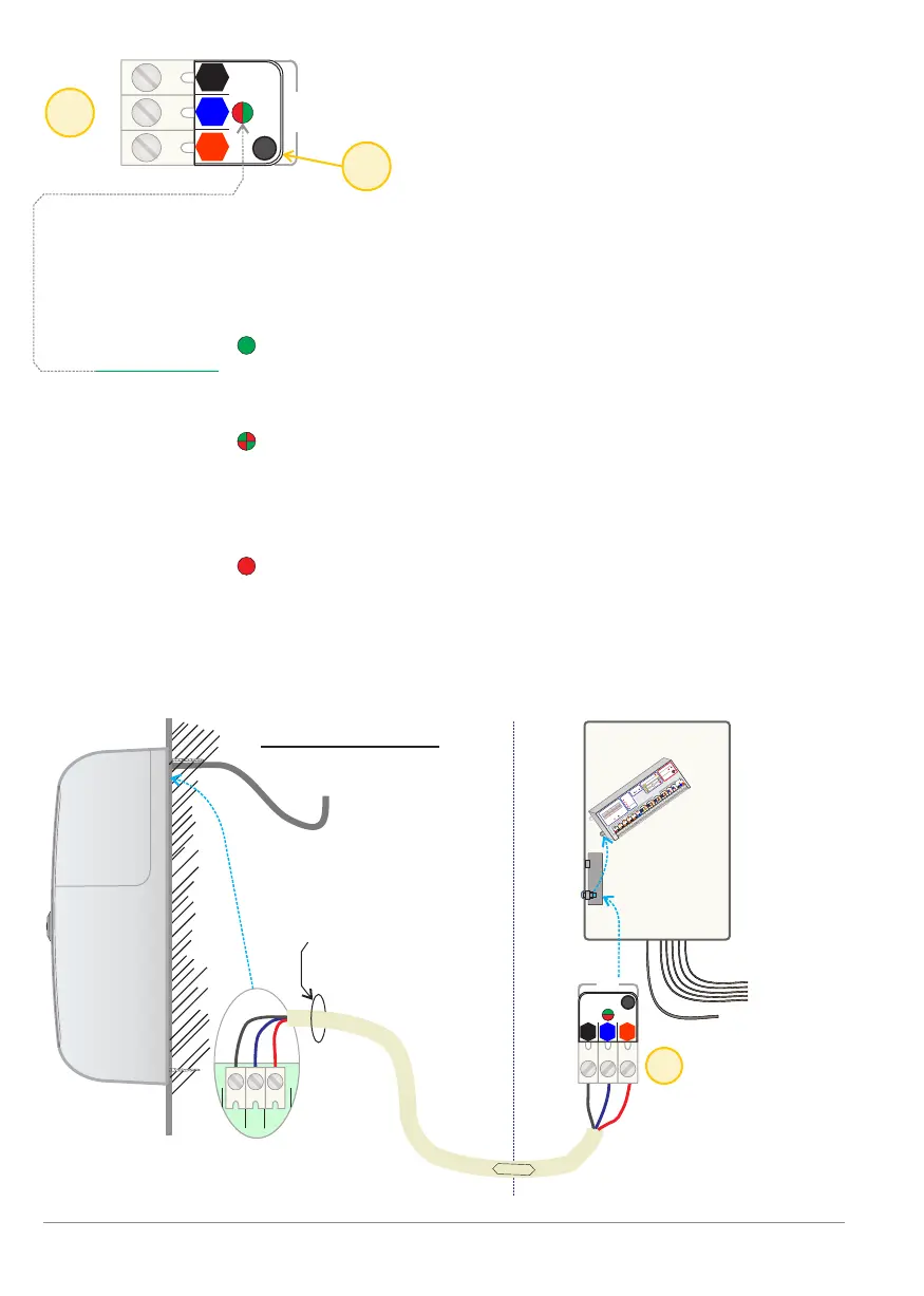
These three terminal connectors enable the controller to communicate with its
installed fog generator. The bus communication takes place via encrypted
digital three-wire connection.
Properties of Communication. [Fog]:
- The Comm.LED: Is continuous green as long as the communication
between controller and fog generator is progressing
normally.
Flashing red / green: technical communication is
normal, but there is a problem with the acceptance
of the fog generator. See next page. 21: Setting
procedure for communication.
A continuous red light means that is a fatal
communication error exists.
The electrical connection is broken. The [OK] and
Tamper output [Tamper] will switch to inactive
(COM and NO open).
Connections
M5
BANDIT Controller CF31 v2 / Manual v.102