SETTINGS AND CONTROL
1
1
2
2
3
3
4
4
1 2 3 1 2 3 1 2 31
1
2
2
3
3
4
4
1 2 3 1 2 3 1 2 3
Settings:
Front
Inputs
Inputs
M³
Move
PanBut.
Dip change
Dip change
Read dips
Read dips
G
G
A
A
C
C
F
F
2
3
1 2
3
X Y 1
1
1
2
2
3
3
4
4
1 2 3 1 2 3 1 2 3
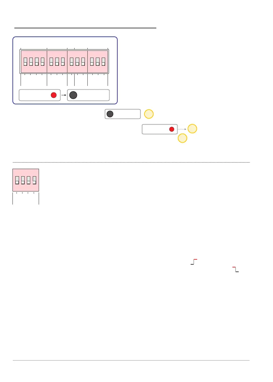
Block: inputs [inputs]
This block selects whether the respective input is active when
applying 12 VDC or when no voltage is present on the input
terminals.See also the section: Inputs from p. 4.
Dip G: Configuration of guard input [Guard].
- ON - Monitoring mode is active when 12 V is on [Guard] terminals.
- OFF - Monitoring mode is active when 0 V (no voltage) is on [Guard]
terminals.
Dip A: Configuration of alarm input [Alarm] (start pulse).
- ON - Alarm mode starts when 12 V is on [Alarm] terminals.
- OFF - Alarm mode is starts when 0 V (no voltage) is on [Alarm]
terminals.
Dip C: Configuration of confirmation input [Conf.].
- ON - Confirmation is provided when 12 V is on [Conf.] terminals.
- OFF - Confirmation is provided when 0 V (no voltage) is on [Conf.]
terminals.
Dip F: Configuration of fire input [Fire].
- ON - Fire mode is active when 12 V is on [Fire] terminals.
- OFF - Fire mode is active when 0 V (no voltage) is on [Fire] terminals.
15
16
15
p. 22 - Dip switch settings
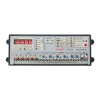
Settings: DIP switch
settings
13 dip switches are divided into
five blocks. Below is a description
the function of each dip switch.
Only after pressing the button will a new dip-switch setting
be read and executed.
When a dip-switch is altered, the red LED lights until
the Read dips button has been pressed. This red LED reminds you that a
dip has changed position without the new state actually loaded and running.
ON
ON
BANDIT Controller CF31 v2 / Manual v.102