After installation, check the control
voltages on the inputs.
- Consider < 2 V as no voltage present.
- Consider > 9 V as 12 VDC voltage
present.
Voltage readings between 2 and 9 VDC
are not normal and will sooner or later
give problems.
In order to function, the controller requires a 12 VDC supply voltage, which
is normally supplied from the existing control panel.
The maximum current is 1A. [ ].
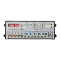
LED off: supply voltage is less than 9.5 volts or reversed.
Red LED on: supply voltage is less than 11 volts (9.5 ~ 11 VDC)
Green LED on: supply voltage is OK (11 ~ 14.4 VDC).
Red LED flashes: power supply voltage is too high (> 14.4 volts).
At a supply voltage of > 18 volt, an internal overvoltage / overcurrent
protection will trip (return to factory and with no warranty).
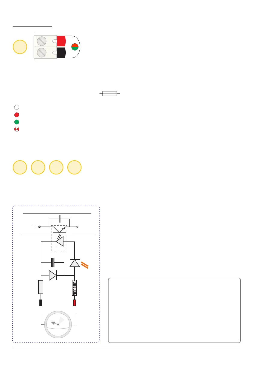
All control inputs are equipped with opto-couplers. This is an excellent
separation between the internal electronics of the BANDIT and the
“outside world".
VDC
12
V+ V-
1
2 3 4 5
Input: 12 VDC supply
opto
LED input
-
+
ground
Schmitt-input
Aircoil
Schematical presentation of an input
1
1
5
1
5
1
V =
INPUTS
Electrical characteristics:
- Polarisation (+ and - signs).
- Reverse polarity protection and RC and
LC filter provided.
- An input should be stable for at least
0.2 seconds for the new state to be
accepted.
- The input current at 12 V is ~ 6 mA per
input.
p. 4 - Inputs
Control inputs
Ω
1 AT
BANDIT Controller CF31 v2 / Manual v.102