EasyManua.ls Logo

Bandit CF31 - User Manual

Bandit CF31
40 pages
Print Icon
To Next Page IconTo Next Page
Loading...
World leader
in active security
INSTALLATION
MANUAL
CONTROLLER
CF31 v2
BANDIT
1 2 3 4 1 2 3 1 2 3 1 2 31 2 3 4 1 2 3 1 2 3 1 2 3
Status:
Alarm
Guard
Panic
Beep
Fire
Fog isolation
Fog control:
BA
CF31 v2
BANDIT
www.bandit.be
Force ejection
Cartridges:
Front
Settings:
Front
Inputs
Move
PanBut.
V+
V-
Error
VDC
12
11 / 14 vdc
Guard
Alarm
Conf.
G+
A+
C+
G-
C-
Fire
F+ F-
Power
no
com
OK
nc no
Tamper
com
Empty
no
com
no
com
PanBut.
Inputs
Outputs
A-
Alarm
Guard
Panic
Fog isolation
Fog control:
Force ejection
Guard
Alarm
G+
A+
G-
A-
Panic
Fog isolation
Fog control:
Force ejection
Alarm
A+
Fog
nc
Cover
Moved
PanBut.
T
o Fog
Tamper
Reset
Comm.
Dip change
Read dips
nc no
com
Guard
no
com
Alarm
nc
1
2 3
Comm.
G
A
C
F
2
3
1 2
3
X Y 1
1 2 3 4 1 2 3 1 2 3 1 2 3
BANDIT Controller CF31 v2 / Installation manual v.102
GB
Question and Answer IconNeed help?

Do you have a question about the Bandit CF31 and is the answer not in the manual?

Summary

Introduction to the Bandit CF31 v2 Controller

Modular Design and Concept

Explains the separated fog generator and controller setup for flexible installation.

Controller Properties and Approvals

Details controller features, certifications like EN 50131-8, and manufacturer information.

Control Panel Layout and Components

Input and Output Terminals

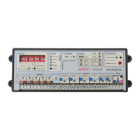
Identifies all input and output connection points on the controller panel.

Status Indicators and DIP Switches

Explains the function of LEDs for status, fog control, and the purpose of DIP switches.

Controller Input Configurations

Power Supply Input

Specifies the 12 VDC power requirements, current, and LED indicators for voltage status.

Guard Input Operation

Configures the Guard input for monitoring mode, detailing its control logic.

Alarm and Confirmation Inputs

Details alarm input for activation and confirmation input for delaying alarm mode.

Fire and Panic Inputs

Configures fire input to block ejection and panic input for emergency activation.

Input Function Flowchart

Visual summary of input relationships and their effect on fog ejection.

Controller Output Functions

Monitoring and Alarm Outputs

Reports monitoring and alarm/panic status via relay contacts and LEDs.

Tamper and Technical Outputs

Indicates tamper faults and general technical problems via relay contacts and LEDs.

Empty and Power Outputs

Notifies about empty cartridges and mains power status.

Communication and System Settings

Fog Generator Communication

Describes the 3-wire communication interface, setup, and status indicators.

DIP Switch Configuration

Explains the function of all DIP switches for input, volume, and LED settings.

Fog Volume and Motion Control

Configures fog volume and motion sensor sensitivity via DIP switches.

Status, Cartridges, and Classification

Cartridge Information and Status

Details cartridge types, installation, and status indicators.

Status and Fault LED Indicators

Explains the meaning of all LEDs for status, errors, and faults on the controller.

Fog Control and Security Classification

Covers fog isolation, forced ejection, and SFVP security level classification.

Installation Examples

Example 1: Basic Alarm System

Shows connecting to an alarm system with specific DIP settings.

Example 2: With Confirmation Sensor

Demonstrates integration with an alarm system and a PIR confirmation sensor.

Example 3: With Panic Button

Illustrates connecting the system with a BANDIT panic button and dialler.

Bandit CF31 Specifications

General IconGeneral
BrandBandit
ModelCF31
CategoryController
LanguageEnglish