Description:
Alarm panel connections:
- 12 V supply: possibly through fuse 1AT (slow).
- Monitoring output: the output relay is open as long as the alarm panel
is not monitoring and closed as long as it is in monitoring status.
- Alarm output: the output relay is open as long as the alarm panel is not
in an alarm condition and switches to closed when in alarm.
- Tamper: Tamper is detected when the loop is interrupted.
- Dialler input 1: OKout output: Technical failures / problems are reported
to the dialler when NO contact opens.
- Dialer input 2: Empty fog cartridge or "no power to fog generator".
Both problems are reported together to the dialler when one or both
NO contact ([Empty] or [Power]) opens.
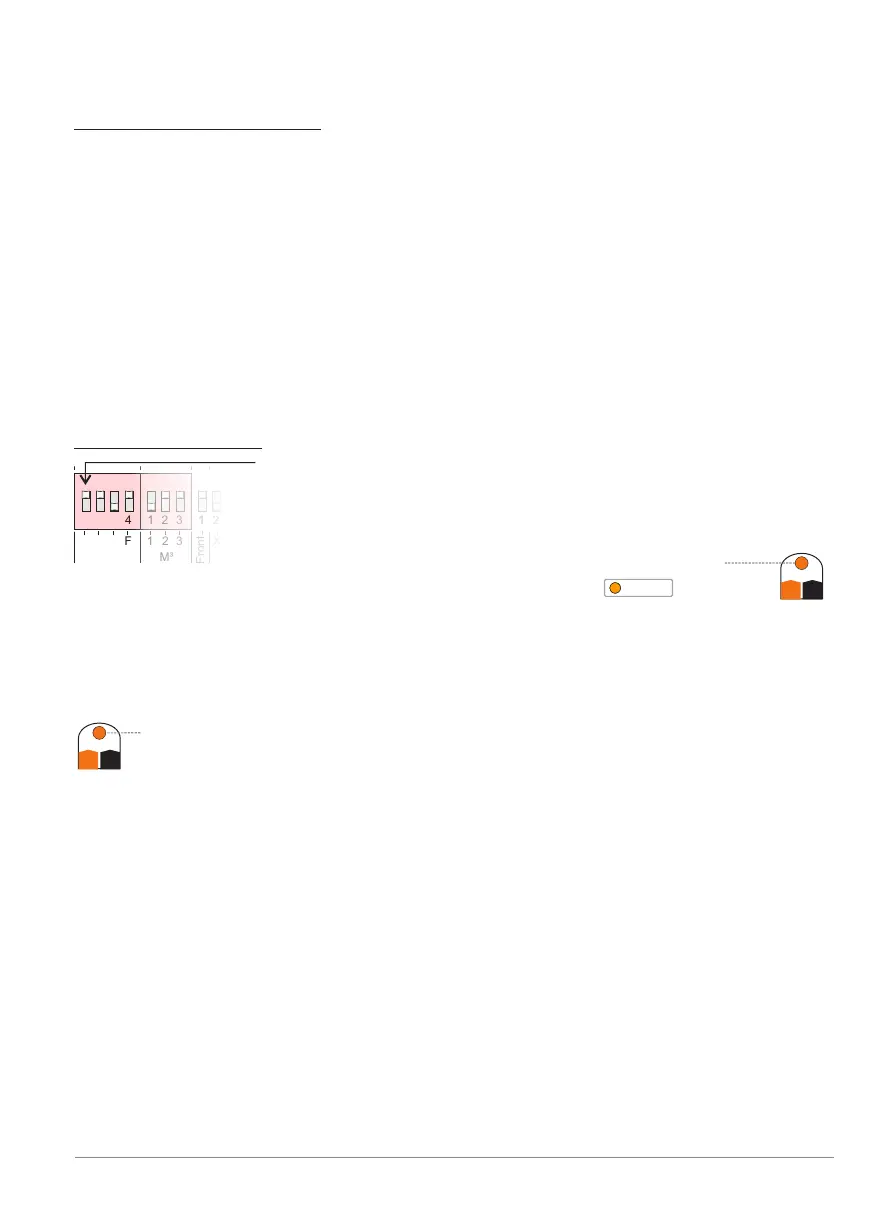
Dip switch settings:
Dip G: is ON = the controller and the fog generator are in
monitoring mode as long as there is 12 VDC provided to
the Guard input [Guard].
As long as the controlling alarm system's monitoring
contact closes, the orange Guard LED will light
and BANDIT is in monitoring mode .
Dip A: is ON = the controller and the fog generator are in alarm mode
(Incl. fog ejection) as long as there is 12 VDC provided to the alarm
input [Alarm].
So when the alarm system closes its alarm contact, the orange
Alarm LED will light and BANDIT remains in alarm mode until
removal of monitoring mode.
Dip C: is OFF = the confirmation input is not connected, so there is never
going to be 12 VDC on the confirmation input [Conf.]. The controller
thus receives continuous acknowledgement to switch to alarm mode.
Dip F: is ON = the fire input is not connected, so there is never going to be
12 VDC on the Fire input [Fire]. So the fire input is never active to thus
prevent a fog ejection.
Dip switch block M³ is OFF-ON-ON as an example, the fog generator is
programmed for a fog ejection and associated cartridges of 100 to 120 m³
(See p. 23).
Guard
G+ G-
Alarm
A+ A-
1 2 3 4 1 2 3 1 21 2 3 4 1 2 3 1 2
Front
Inputs
M³
G
A
C
F
2
3
X1
1 2 3 4 1 2 3 1 2
Installation example 1 - p. 33
GuardGuard
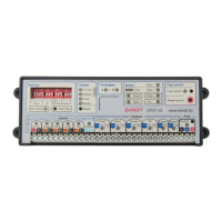
BANDIT Controller CF31 v2 / Manual v.102