5
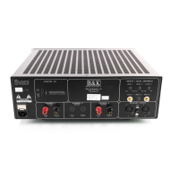
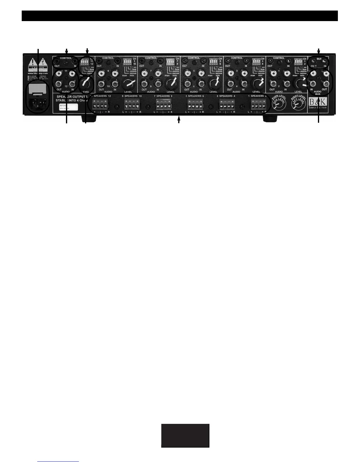
1. AC Power Inlet and AC Fuse. The fuse is an 8 Amp / 250 Volt Slow Blow fuse. Replace with same
type and value fuse only.
2. Channel control input/output. Each pair of amplifier channels has its own 1/8” (3.5mm) minijack control
input/output (pass through) control jack to provide remote switching of the amplifier audio mute on/off
feature. The control input circuit is designed to work as Tip Pos. (+) and Ring Neg. (-). A minimum of
5VDC @ 1 mA is recommended, and is compatible with up to 24V AC or DC. (The control outputs DO
NOT source any voltage directly, they only PASS through the input voltage at their receptive inputs).
3. Channel inputs and outputs. Each pair of amplifier channels has its own set of audio input / output
(pass through) RCA connections. Typically used for connecting signal interconnects from the preamplifier
to the amplifier.
4. Dip Switches. Each pair of amplifier channels has its own Dip Switches that are used to configure the
audio signal (Local or Bus, mono or stereo, muting sense and control trigger).
5. Channel level control. Each pair of amplifier channels has its own DUAL input level control. The level
of the right channel is adjusted by the outer level control and the level of the left channel is adjusted
by the inner level control. This is also shown on the back panel of the unit.
6. Removable four position phoenix speaker connections. Speaker connections are 4 ohm stable.
Connectors can accommodate up to 12 gauge speaker wire.
7. Bus control input/output. The amplifier allows for single switching of the amplifier audio mute on/off
feature on any pair of amplifier channels (1-2, 3-4, 5-6, 7-8, 9-10, 11-12) with it’s Dip Switch setting
configured for Amp off and Sense off. The Bus control output is a pass through of the Bus control
input. The control input circuit is designed to work as Tip Pos. (+) and Ring Neg. (-). A control source
capable of sourcing a minimum of 5 VDC @ 1 mA is recommended, and is compatible with up to 24V
AC or DC. (The control outputs DO NOT source any voltage directly, they only PASS through the input
voltage at their receptive inputs).
8. Bus inputs and outputs. In a similar fashion to the Bus control inputs, the AV1230 has provisions for
an independent stereo audio signal and control trigger distribution bus. It is an independent stereo
audio input and minijack control input and output to source audio and trigger to amplifier channels
1-2, 3-4, 5-6, 7-8, 9-10, or 11-12 when the Dip Switch for Bus is set to On.
1
2
4
3
5
6
7
8
 Loading...