Preliminary Information
Banner Engineering Corp • Minneapolis, MN USA www.bannerengineering.com • Tel: 763.544.3164
Sensonix Incorporated • Plymouth, MN USA
7 of 18 www.sensonix.com • 763.519.7042
2.6 ModBus Communications, RS232 / 485 (model LPGW1)
The gateway interface is controlled using the Modbus RTU protocol. The gateway device operates as
a Modbus slave device with a programmable slave address in the range of 01-99. The serial interface is set
up with factory default parameters of 19.2k baud, one start bit, two stop bits, no flow control and a slave
address of ‘01’.
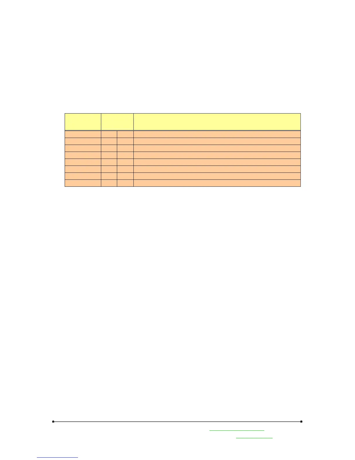
The following Modbus function codes are supported. For DX80 configuration commands and DX80
user commands refer to the DX80 Interface Protocol document.
Type
Function
Code
Description
Modbus Cmd 1 0x1 Read Coils, 1 – 2000 contiguous status of coils
Modbus Cmd 2 0x2 Read Discrete Inputs, 1 – 2000 contiguous status of discrete inputs
Modbus Cmd 3 0x3 Read Holding Registers, 1 – 125, contiguous block of holding regs.
Modbus Cmd 4 0x4 Read Input Registers, 1 – 125, contiguous block of input registers
Modbus Cmd 5 0x5 Write Single Coil
Modbus Cmd 6 0x6 Write Single Register
Modbus Cmd 15 0xF Write Multiple Coils, 1 – 0x7B0 force multiple coils, ON or OFF
Modbus Cmd 16 0x10 Write Multiple Registers, 1 – 0x78, contiguous block of registers
The gateway front panel LED’s are used to display information about the Modbus serial
communications.
LED1
• ‘GREEN’ when power is applied and the gateway is operational.
• ‘RED’ indicates a system error has occurred. Review the LCD display for further
information.
LED2
• ‘YELLOW’ signifies a frame reception or sending.
• ‘RED’ signals an internal Modbus error has occurred.
• Flashing ‘RED’ indicates a communications fault or configuration error.
The RS485 connections are on the 12-pin euro-style male connector QD2 on the gateway. See the Euro
Connector Diagram section in this manual