P/N 69761 rev. B 9
Banner Engineering Corp. • Minneapolis, U.S.A.
www.bannerengineering.com • Tel: 763.544.3164
PICO-GUARD Controller
Instruction Manual
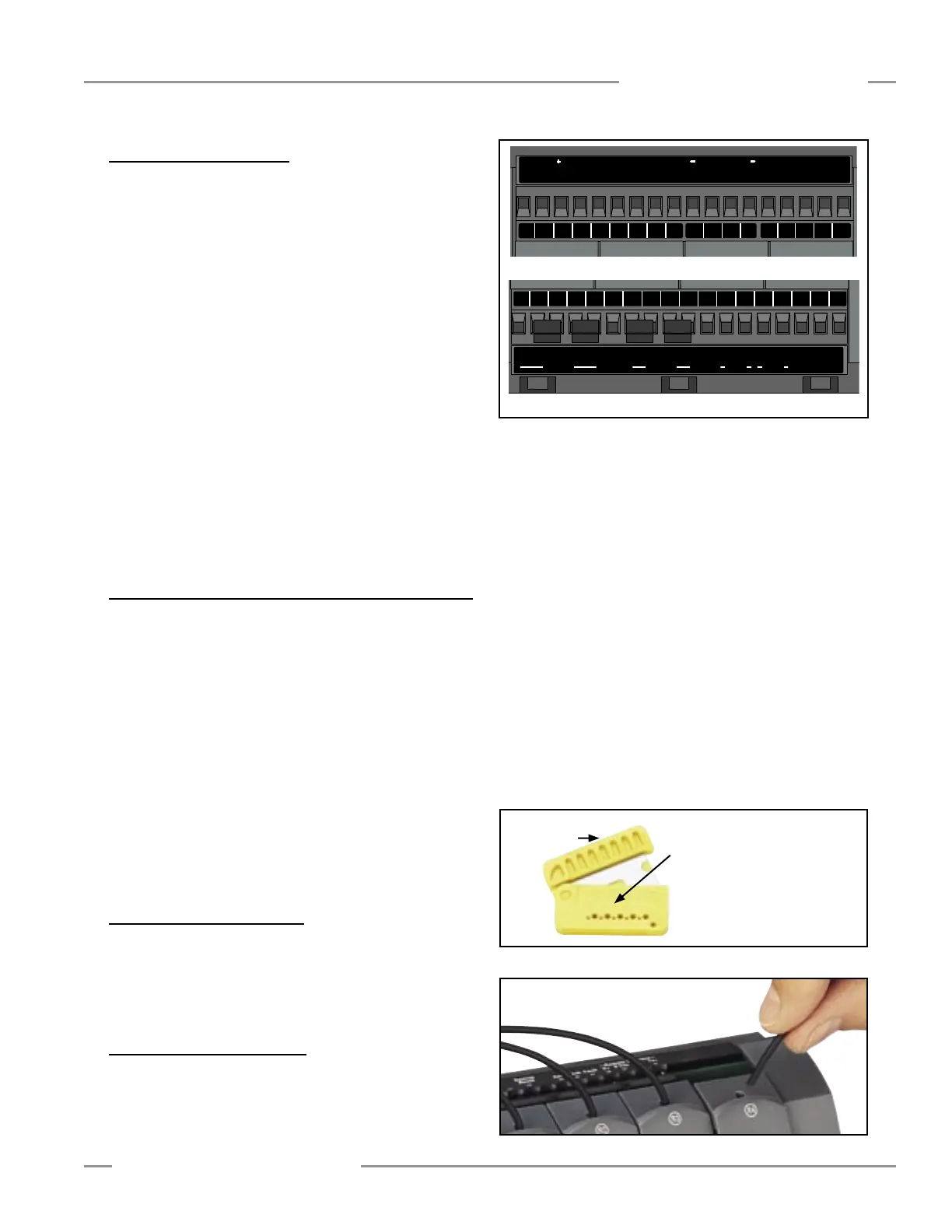
Figure 3-1. Controller terminal locations
Transparency is used on this drawing...
(scaled down to 1/2)
Reset
a-b c-d a-b c-d
a-b a-b
1 2
USSI 1 USSI 2 EDM 1 O
SSDEDM 2
ChannelSystem
1 2 3 4Status Reset
Banner Engineering Corp., USA
www.bannerengineering.com
FCDT-4A1 PICO-GUARD Controlle
FCDT-4A1 PICO-GUARD Controlle
763-544-3164
Correct use of this control device is an essential part of
proper machine control. Always follow the instructions in the
manual. Failure to follow all instructions or warnings could
lead to serious bodily injury or death.
WARNING
24Vdc, 0.5A
Channel 13ms; USSI 7m
s
IEC IP20, NEMA
1
0 - 50
C
24Vdc, 0.5A
24Vdc, 0.25A
Cat. 4 (ISO 13849 / EN954),
Type 4 (IEC 61496-1, -2)
Rated Supply:
Response Time
:
Enclosure Rating:
Te
mperature Rating:
OSSD Rating:
Device Type:
Aux, Weak, Fault Rating:
1 2 3 4 5 7 8 9 10 12 13 14 15 17 18
1
2 3 4 5 7 8 9 10 12 13 14 15 17 1
8
OSSDEDM 1USSI 2USSI 1
1 2a b c d
Reset
EDM 2
a b a ba b c d
313029272625232120 28
Tx-0 Vdc Tx+Reset
24
Vd
c
0
Vdc Aux
Weak Fault
Remote Interface
V+
36
353433
Ch3Ch2 Ch4
Ch
1
System
272625232120
31302928
36353433
R1
R2
R3
R4
E1
E2
E3
E4
35 mm
66 mm
(2.6")
132 mm
(5.2")
93.8 mm
(3.69")
112.4 mm
(4.43")
7 mm
(0.27")
122.6 mm
(4.78")
85.5 mm
(3.37")
3.4 Electrical Connections
Make the electrical connections in the order described in this
section.
NOTE: PICO-GUARD wiring is low voltage; running these wires
alongside power wires, motor/servo wires, or other
high-voltage wiring can inject noise into the
PICO-GUARD System. It is good wiring practice (and
may be required by code) to isolate PICO-GUARD
System wires from high-voltage wires.
For easy wiring, the controller has removable modular terminal
blocks. These terminal blocks can accept individual conductors
from #26 to #12 AWG (0.2 mm2 to 2.5 mm2) or two stranded
conductors from #26 to #14 AWG (0.2 mm2 to 1.5 mm2). The
wires used should have an insulation temperature rating of at
least 90° C (194° F).
To connect wires to the terminal blocks strip the individual wire
insulation approximately 6 mm (0.25") and make connections
to terminals as directed in the following sections. Torque
each terminal screw to 0.57 to 0.90 Nm (5 to 8 in.-lbs.)
recommended torque.
Refer to Figures 3-7, 3-8, 3-9 and 3-10.
3.4.1 System Reset and USSI 1 Reset Switch Hookup
The System Reset and USSI 1 Reset switches are generally
individual switches to allow separate control of the two reset
functions (see Section 4.3 for reset procedures).
The System Reset and USSI 1 Reset switches may be a
single switch, but must use electrically isolated normally
open contacts (e.g., DPST or 2-Form-A). The reset inputs are
monitored such that a short circuit between terminals 1 and 23
will cause a lockout condition, but will allow connection to a
common source of +24V dc. Refer to Figures 3-7, 3-8, 3-9 and
3-10.
Connect the external System Reset switch to the System Reset
terminal (23) and to the +24V dc supply.
Connect the USSI 1 Reset switch (if used) to the USSI 1 Reset
terminal (1) and to the +24V dc supply.
3.4.2 System Power Hookup
DO NOT apply power to the controller at this time. Power will
be applied during the initial system checkout.
Connect the system power wires to the +24V dc terminal (21)
and the 0V dc terminal (20).
3.5 Optical Fiber Installation
Use only the Banner fiber optic cable listed in Section 2, or
call Banner factory applications department to determine fiber
suitability. For best operation, minimize the fiber lengths,
number of splices, number of tight bends and operating
distance of the optical devices. See Section 3.1 of this manual
and also see the PICO-GUARD Application and Design Guide.
If using the unsheathed fiber, each fiber must be installed such
that the black jacket of the optical fiber is protected from nicks,
cuts or crushing; each fiber must be routed separately.
If using PVC sheathed fiber, sheathing must be removed
without damaging the black jacket of the fiber; a 10 gauge or 3
mm (0.12") wire stripper is recommended. Remove
15-20 mm (0.6" to 0.75") of the PVC sheath from each end of
the fiber to allow proper insertion into the optical elements and
controller.
Use the Banner plastic fiber cutter model PFC-2 to make
finished cuts to minimize signal loss. Polished fiber lengths
are available for maximum excess gain (see Section 2.2). Use
each cutting port only once.
To connect the fibers to the controller, simply slide the cap to
open the fiber ports, push the prepared fiber in as far as it will
go, then slide the fiber port closed (see Figure 3-3).
Top View
Bottom View
Figure 3-2. Trimming the fibers with the Model PFC-2 Fiber Cutter
Transparency is used on this drawing...
(scaled down to 1/2)
Reset
a-b c-d a-b c-d
a-b a-b
1 2
USSI 1 USSI 2 EDM 1 O
SSDEDM 2
ChannelSystem
1 2 3 4Status Reset
Banner Engineering Corp., USA
www.bannerengineering.com
FCDT-4A1 PICO-GUARD Controlle
FCDT-4A1 PICO-GUARD Controlle
763-544-3164
Correct use of this control device is an essential part of
proper machine control. Always follow the instructions in the
manual. Failure to follow all instructions or warnings could
lead to serious bodily injury or death.
WARNING
24Vdc, 0.5A
Channel 13ms; USSI 7m
s
IEC IP20, NEMA
1
0 - 50
C
24Vdc, 0.5A
24Vdc, 0.25A
Cat. 4 (ISO 13849 / EN954),
Type 4 (IEC 61496-1, -2)
Rated Supply:
Response Time
:
Enclosure Rating:
Te
mperature Rating:
OSSD Rating:
Device Type:
Aux, Weak, Fault Rating:
1 2 3 4 5 7 8 9 10 12 13 14 15 17 18
1
2 3 4 5 7 8 9 10 12 13 14 15 17 1
8
OSSDEDM 1USSI 2USSI 1
1 2a b c d
Reset
EDM 2
a b a ba b c d
313029272625232120 28
Tx-0 Vdc Tx+Reset
24
Vd
c
0
Vdc Aux
Weak Fault
Remote Interface
V+
36
353433
Ch3Ch2 Ch4
Ch
1
System
272625232120
31302928
36353433
R1
R2
R3
R4
E1
E2
E3
E4
35 mm
66 mm
(2.6")
132 mm
(5.2")
93.8 mm
(3.69")
112.4 mm
(4.43")
7 mm
(0.27")
122.6 mm
(4.78")
85.5 mm
(3.37")
Figure 3-3. Installing the prepared fiber ends into the controller
Installation and Alignment
Lift to
open ports
Cutting Ports
5 - Large
5 - Small
NOTE: Use each cutting port
only once; hold fibers
perpendicular while cutting

 Loading...


