16 P/N 69761 rev. B
Banner Engineering Corp. • Minneapolis, U.S.A.
www.bannerengineering.com • Tel: 763.544.3164
PICO-GUARD Controller
Instruction Manual
S1
S2
Y1
Y2
Y3
Y4
14
24
34
13
23
33
S4
S3
IM-T-9A
K2 K1
MPCE
2
Feedback (optional)
MPCE
1
Machine
Control
Load
Load
Load
Aux
Weak
Fault
Safety Device
Solid-State
Outputs
+V OV
+24V dc
0V dc
0V dc
+24V dc
EDM2a
EDM2b
EDM1a
EDM1b
OSSD1
OSSD2
PICO-GUARD
Controller
+
+
System Reset
USSl 1 Reset
(2)
21 20
25
26
27
12
13
14
15
18
17
23
1
RS-232
Diagnostics
(1)
(3)
(3)
Tx-
Tx+
a
c
d
b
a
c
d
b
USSl 1
Input
USSl 2
Input
31
30
29
28
10
8
5
4
2
3
Remote
Interface
+V
OVdc
Safety Device
Contact Outputs
+
+
9
7
Load
Load
Load
Load
33
34
35
Ch1*
Ch2*
Ch3*
Ch4*
36
* only for model
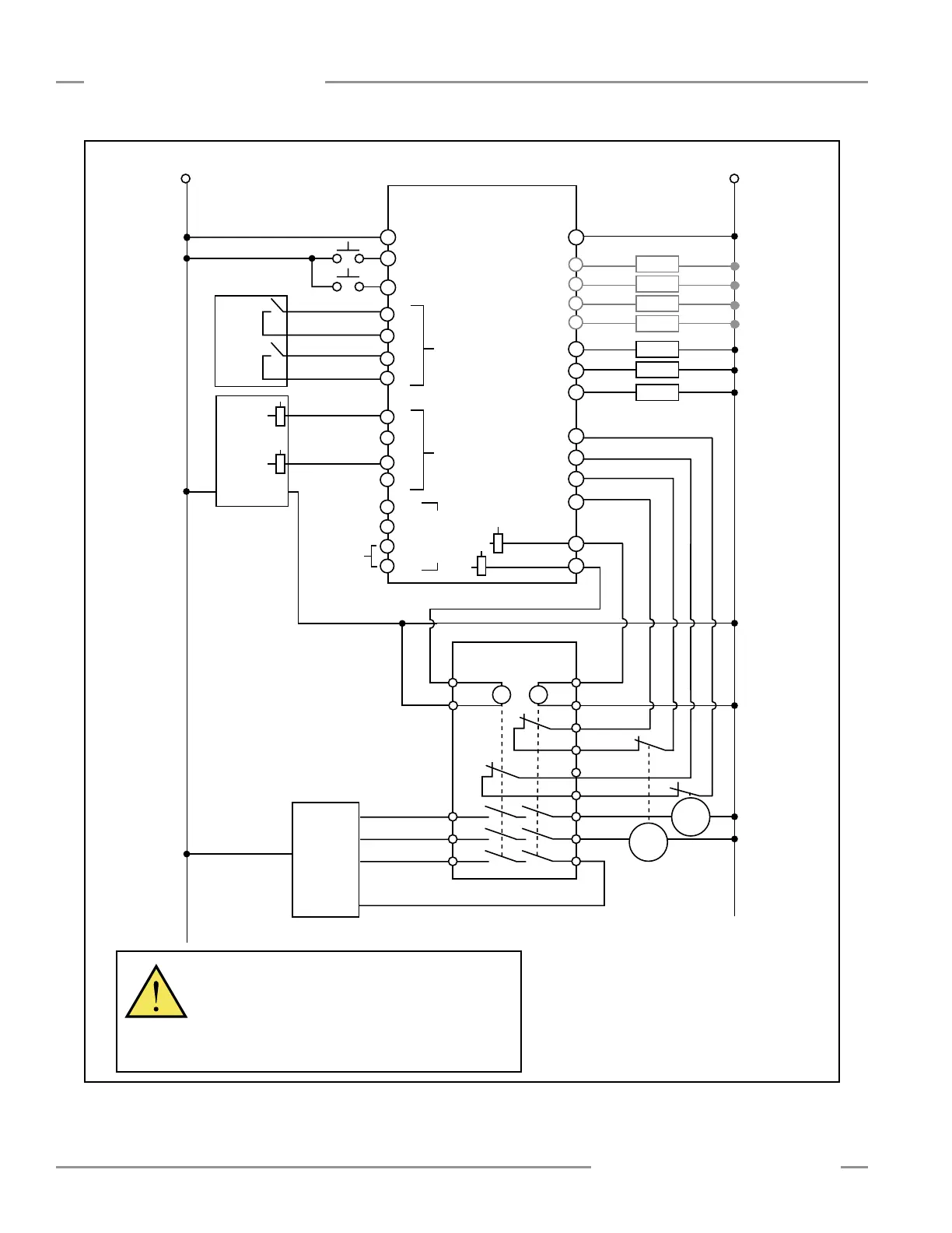
SFCDT-4A1C
(1) See Section 3.4.1 for
information on Reset input
and hookup.
(2) 2-Channel EDM shown. See
Section 3.9.3 for information
on EDM input and hookup.
(3) Must meet External Stop
Device requirements.
See Section 3.7.
Figure 3-8. PICO-GUARD System interface module (IM-T-9A) hookup; two-channel EDM
WARNING… Arc Suppressors
Never install arc suppressors directly across the
output contacts of any safeguarding device. If arc
suppressors are used, they must be installed across the
load. It is possible for the suppressors to fail as a short
circuit.
Installation and Alignment

 Loading...


