P/N 69761 rev. B 21
Banner Engineering Corp. • Minneapolis, U.S.A.
www.bannerengineering.com • Tel: 763.544.3164
PICO-GUARD Controller
Instruction Manual
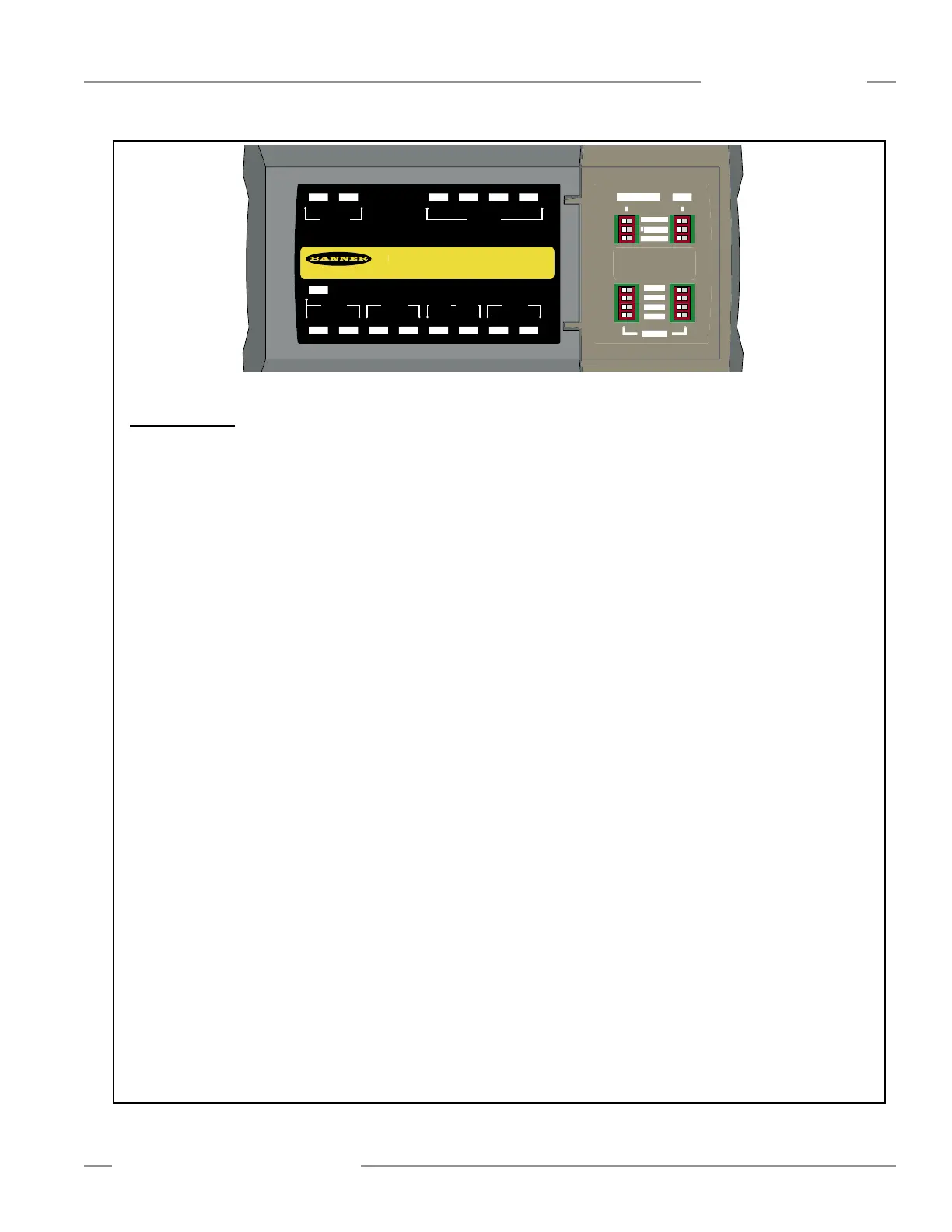
Figure 4-3. PICO-GUARD controller status indicators
“System Status” Indicator (bi-color Red/Green): overall status of the
PICO-GUARD system
Green – Run condition
Red – Stop or Latch conditions
Red Flashing – Lockout conditions
Flashing Burst* (Red or Green) – electrical noise in the system
“System Reset” Indicator (bi-color Yellow/Red): status of the System
Reset input or System Reset needed
Yellow Double-Flashing – waiting for system reset after power-up
Yellow Single-Flashing – waiting for system reset after latch condition
Yellow – input signal is high
Red Flashing – external fault of the input detected
OFF – input signal is low or during lockout (except for System Reset
faults)
Red Flashing Burst* – noise on the System Reset input
Optical “Channel” Indicators (bi-color Red/Green): status of the optical
channels (one indicator for each optical channel)
Green – channel is closed (clear)
Green Double-Flash – channel was interrupted, but is closed again
(latch mode only)
Flickers Green – weak or marginal signal
Red – channel is open (blocked)
Red Flashing – channel fault detected
OFF – channel is disabled or during lockout (except for optical channel
faults)
Flashing Burst* (Red or Green) – noise on the channel
“USSI” Indicators (bi-color Red/Green): status of the USSI input
channels (a-b and c-d), two indicators per USSI input (one for each input
channel)
Green – an input channel is closed (high)
Red Flashing – external fault of the input channel detected
Both Synchronized Red Flashing – fault detected, but the specific input
channel cannot be determined
OFF – an input channel is open (low) or during lockout (except for
USSI channel faults)
Flashing Burst* (Red or Green) – noise on the input channel
“USSI 1 Reset” Indicator (bi-color Yellow/Red): status of the USSI 1
reset input, or USSI 1 reset needed
Yellow – input signal is high
Yellow Flashing – waiting for USSI 1 latch reset
Red Flashing – external fault of the input detected
OFF – input signal is low or during lockout (except for USSI 1 Reset
faults)
Red Flashing Burst* – noise on the USSI 1 reset input
“EDM” Indicators (bi-color Red/Green): status of the EDM inputs (one
indicator for each input)
Green – input signal is high
Red Flashing – external fault of the input detected
Both Synchronized Red Flashing – EDM fault detected; specific input
cannot be determined
OFF – input signal is low or during lockout (except for EDM input
faults)
Flashing Burst* (Red or Green) – noise on an EDM input channel
“OSSD” Indicators (bi-color Red/Green): status of each OSSD output
(one indicator for each output)
Green – OSSD is ON
Red – OSSD is OFF
Red Flashing – external output fault detected
Both Synchronized Red Flashing – specific OSSD output fault cannot
be determined
OFF – lockout (except for OSSD output faults)
“Config” Indicator (bi-color Red/Green): status of the system
configuration
Green – configuration switch state is valid
Red Flashing – configuration switch state is invalid
OFF – lockout (except for configuration faults)
* A flashing burst is three short consecutive flashes, followed by
a pause.
Transparency is used on this drawing...
(scaled down to 1/2)
Reset
a-b c-d a-b c-d
a-b a-b
1 2
USSI 1 USSI 2 EDM 1 OSSDEDM 2
ChannelSystem
1 2 3 4Status Reset
Banner Engineering Corp., USA
www.bannerengineering.com
FCDT-4A1 PICO-GUARD Controlle
FCDT-4A1 PICO-GUARD Controlle
763-544-3164
Correct use of this control device is an essential part of
proper machine control. Always follow the instructions in the
manual. Failure to follow all instructions or warnings could
lead to serious bodily injury or death.
WARNING
24Vdc, 0.5A
Channel 13ms; USSI 7m
s
IEC IP20, NEMA
1
0 - 50
C
24Vdc, 0.5A
24Vdc, 0.25A
Cat. 4 (ISO 13849 / EN954),
Type 4 (IEC 61496-1, -2)
Rated Supply:
Response Time
:
Enclosure Rating:
Te
mperature Rating:
OSSD Rating:
Device Type:
Aux, Weak, Fault Rating:
1 2 3 4 5 7 8 9 10 12 13 14 15 17 18
1
2 3 4 5 7 8 9 10 12 13 14 15 17 1
8
OSSDEDM 1USSI 2USSI 1
1 2a b c d
Reset
EDM 2
a b a ba b c d
313029272625232120 28
Tx-0 Vdc Tx+Reset
24
Vd
c
0
Vdc Aux
Weak Fault
Remote Interface
V+
36
353433
Ch3Ch2 Ch4
Ch
1
System
272625232120
31302928
36353433
R1
R2
R3
R4
E1
E2
E3
E4
35 mm
66 mm
(2.6")
132 mm
(5.2")
93.8 mm
(3.69")
112.4 mm
(4.43")
7 mm
(0.27")
122.6 mm
(4.78")
85.5 mm
(3.37")
System Operation

 Loading...


