Step Interval—Sets the amount of time that the Single Step button advances when pressed. The amount of time is based
on the size of the
configuration.
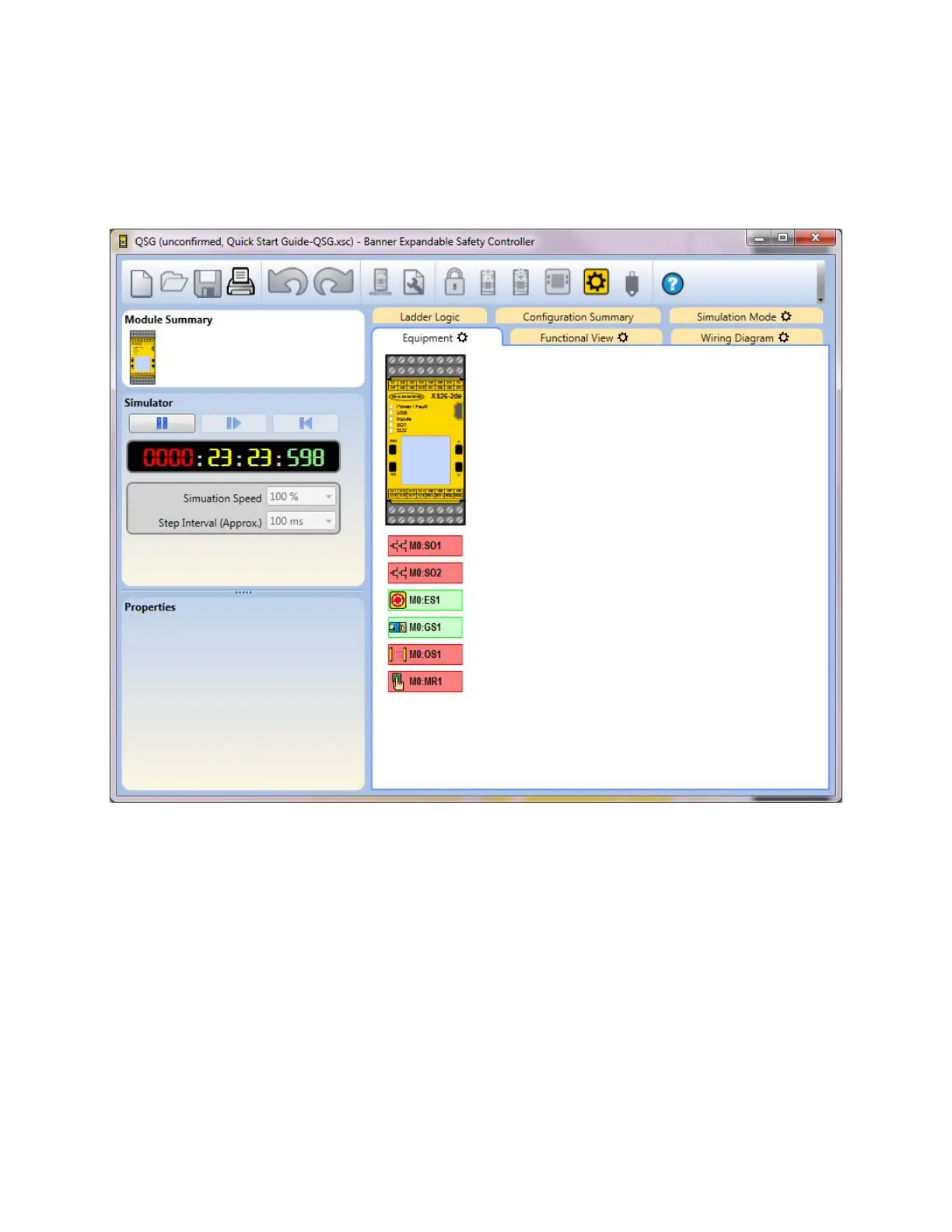
Press Play to begin the simulation. The timer runs and gears spin to indicate that the simulation is running. The Functional,
Equipment, and Wiring Diagram tabs update, providing visual representation of the simulated device states as well as
allowing testing of the configuration. Click on the items to be tested; their color and state change accordingly. Red indicates
the stop or off state. Green indicates the run or on state. Yellow indicates a fault state. Orange indicates that the input was
turned on before the initial start of the simulation. Due to a start-up off test requirement, the input must be seen as off
before it can be recognized as on.
Figure 100. Simulation Mode—Equipment Tab
XS/SC26-2 and SC10-2 Safety Controllers
www.bannerengineering.com - Tel: + 1 888 373 6767 119
 Loading...


