7.3 SC10-2 Applications
The SC10-2 Safety Controller is ideal for any small to medium size machine that would typically use two independent safety
relay modules.
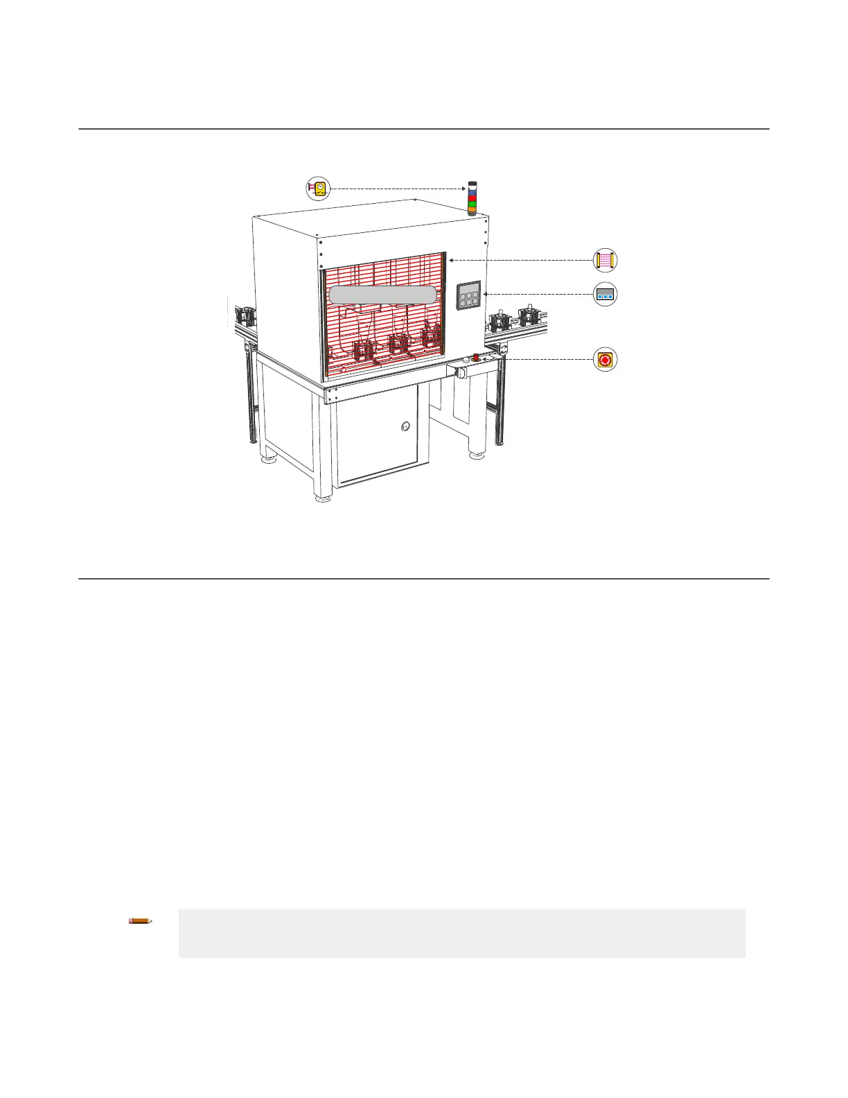
E-Stop Buttons
Safety Light Screens
Muting Indicator Lights
HMI
Hazardous Area
Figure 12. SC10-2 Sample Application
7.4 Safety Input Devices
The Safety Controller monitors the state of the safety input devices that are connected to it. In general, when all of the input
devices that have been configured to control a particular Safety Output are in the Run sate, the Safety Output turns or
remains On. When one or more of the safety input devices change from Run state to Stop state, the Safety Output turns
Off. A few special safety input device functions can, under predefined circumstances, temporarily suspend the safety input
stop signal to keep the Safety Output On, for example, muting or bypassing.
The Safety Controller can detect input faults with certain input circuits that would otherwise result in a loss of the control of
the safety function. When such faults are detected, the Safety Controller turns the associated outputs Off until the faults are
cleared. The function blocks used in the configuration impact the safety outputs. It is necessary to carefully review the
configuration
if the input device faults occur.
Methods to eliminate or minimize the possibility of these faults include, but are not limited to:
• Physically separating the interconnecting control wires from each other and from secondary sources of power
• Routing interconnecting control wires in separate conduit, runs, or channels
• Locating all control elements (Safety Controller, interface modules, FSDs, and MPCEs) within one control panel,
adjacent to each other, and directly connected with short wires
• Properly installing multi-conductor cabling and multiple wires through strain-relief fittings. Over-tightening of a
strain-relief can cause short circuits at that point
•
Using positive-opening or direct-opening components, as described by IEC 60947-5-1, that are installed and
mounted in a positive mode
• Periodically checking the functional integrity/safety function
• Training the operators, maintenance personnel, and others involved with operating the machine and the
safeguarding to recognize and immediately correct all failures
Note: Follow the device manufacturer's installation, operation, and maintenance instructions and
all relevant regulations. If there are any questions about the device(s) that are connected to the
Safety Controller, contact Banner Engineering for assistance.
XS/SC26-2 and SC10-2 Safety Controllers
www.bannerengineering.com - Tel: + 1 888 373 6767 25