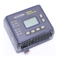
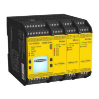
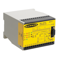
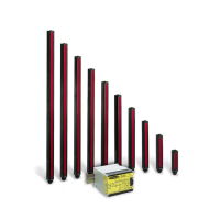
Do you have a question about the Banner SC26-2 and is the answer not in the manual?
Provides critical safety information and user responsibilities for applying the XS/SC26-2 Safety Controller.
Outlines the three main steps for configuring the Safety Controller using the PC Interface.
Lists detailed technical specifications for the controller and expansion modules.
Details the steps required to create and confirm a controller configuration.
Guides on adding safety, non-safety inputs, and status outputs.
Explains the Functional View for creating control logic diagrams.
Details the available Boolean logic blocks for configuration.
Describes pre-programmed function blocks for common application needs.
Steps for designing the control logic by adding inputs and blocks.
Details how to view real-time device and fault information via Live Mode.
Enters configuration mode for SC-XM2 drive operations.
Provides guidelines for installing the Safety Controller, including mounting.
Explains how the Safety Controller monitors safety input devices.
Details safety circuit integrity levels and ISO 13849-1 principles.
Describes the function of various safety input devices and their circuits.
Explains the configuration and function of Solid-State and Safety Relay Outputs.
Details how to find and fix faults using fault codes and messages.
Lists fault codes, displayed messages, and steps to resolve them.
| Type | Safety Controller |
|---|---|
| Input Voltage | 24 V DC |
| Supply Voltage | 24 V DC |
| Output Type | Solid State |
| Number of Outputs | 2 |
| Connection Type | Screw Terminals |
| Protection Rating | IP20 |
| Certifications | CE |
| Housing Material | Plastic |
