6.4.12 Adjustable Valve Monitoring (AVM) Function
The Adjustable Valve (Device) Monitoring (AVM) function is similar in function to One-Channel External Device
Monitoring (1-channel EDM, see External Device Monitoring (EDM) on page 90). The AVM function monitors the state of
the device(s) that are controlled by the safety output to which the function is mapped. When the safety output turns Off,
the AVM input must be high/On (+24 V dc applied) before the AVM timer expires or a lockout will occur. The AVM input
must also be high/On when the safety output attempts to turn On or a lockout will occur.
Adjustable Valve Monitoring AVM is a way to check the operation of dual channel valves. The force
guided N.C. monitoring contacts of the valves are used as an input to detect a “stuck on” fault
condition and will prevent the safety controller outputs from turning On.
Adjustable Valve
Monitoring
100 ms
to
5 sec.
100 ms
to
5 sec.
Don’t Care Don’t Care
Closed
Open
SO1
AVM
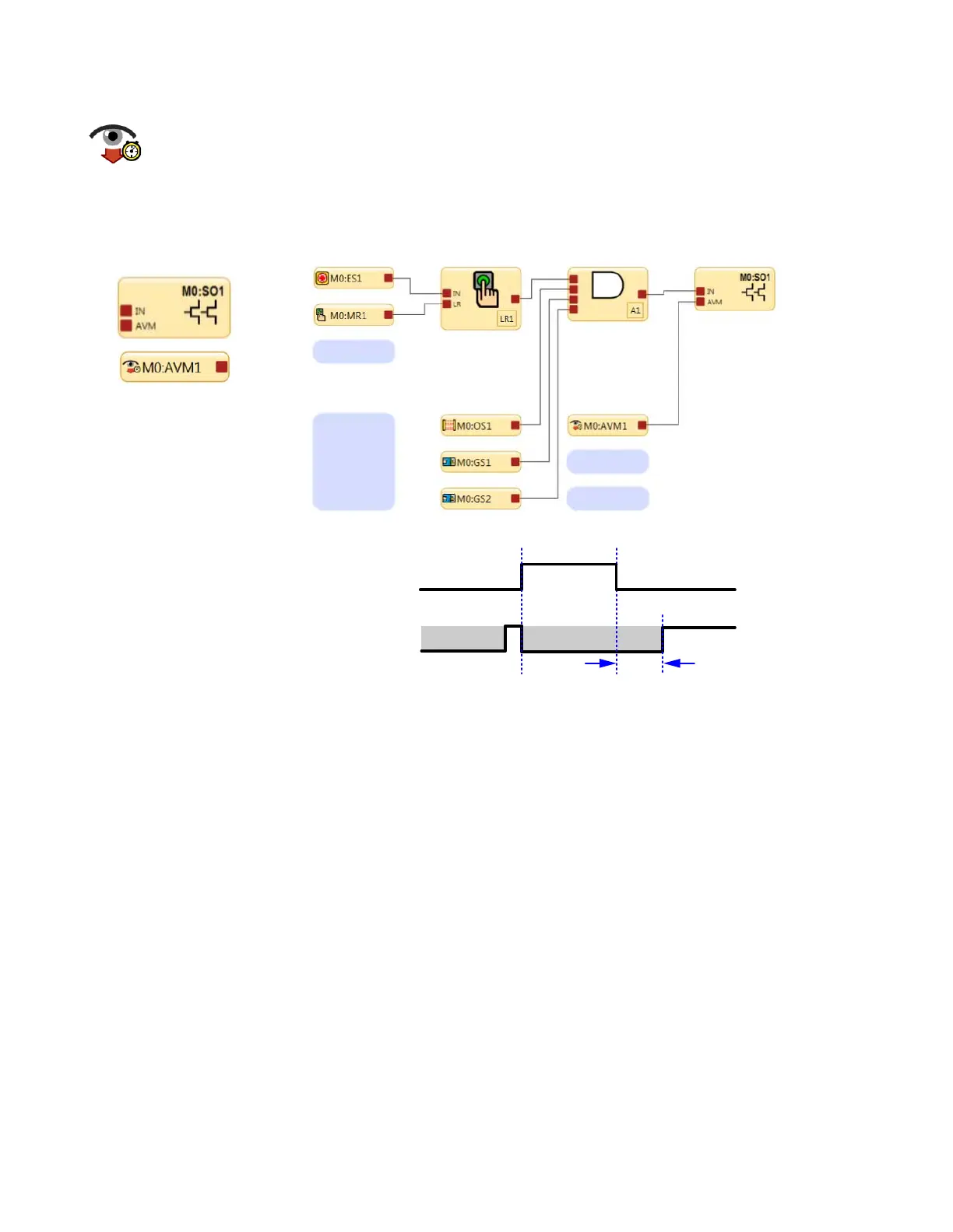
Figure 60. Timing logic—AVM Function
Note: 100 ms to 5 s time period is adjustable in 50 ms intervals (default is 100 ms).
The Adjustable Valve (Device) Monitoring function is useful for dynamically monitoring devices under the control of the
safety output that may become slow, stick, or fail in an energized state or position, and whose operation needs to be
verified after a Stop signal occurs. Example applications include single- or dual-solenoid valves controlling clutch/brake
mechanisms, and position sensors that monitor the home position of a linear actuator.
Synchronization or checking a maximum differential timing between two or more devices, such as dual valves, may be
achieved by mapping multiple AVM functions to one safety output and configuring the AVM timer to the same values. Any
number of AVM inputs can be mapped to one safety output. An input signal can be generated by a hard/relay contact or a
solid-state PNP output.
XS/SC26-2 Safety Controller
82