To remove the XS/SC26-2 Safety Controllers:
1. Push up on the bottom of the module.
2. Tilt the top of the module slightly forward.
3. Lower the module after the top rigid clip is clear of the DIN rail.
NOTE: To remove an expansion module, pull apart other modules on each side of the desired module to
free bus connectors.
6.3 Safety Input Devices
The Safety Controller monitors the state of the safety input devices that are connected to it. In general, when all of the
input devices that have been configured to control a particular Safety Output are in the Run sate, the Safety Output turns
or remains On. When one or more of the safety input devices change from Run state to Stop state, the Safety Output
turns Off. A few special safety input device functions can, under predefined circumstances, temporarily suspend the safety
input stop signal to keep the Safety Output On, for example, muting or bypassing.
The Safety Controller can detect input faults with certain input circuits that would otherwise result in a loss of the control
of the safety function. When such faults are detected, the Safety Controller turns the associated outputs Off until the faults
are cleared. The function blocks used in the configuration impact the safety outputs. It is necessary to carefully review the
configuration if the input device faults occur.
Methods to eliminate or minimize the possibility of these faults include, but are not limited to:
• Physically separating the interconnecting control wires from each other and from secondary sources of power
• Routing interconnecting control wires in separate conduit, runs, or channels
• Locating all control elements (Safety Controller, interface modules, FSDs, and MPCEs) within one control panel,
adjacent to each other, and directly connected with short wires
• Properly installing multi-conductor cabling and multiple wires through strain-relief fittings. Over-tightening of a
strain-relief can cause short circuits at that point
• Using positive-opening or direct-opening components, as described by IEC 60947-5-1, that are installed and
mounted in a positive mode
• Periodically checking the functional integrity/safety function
• Training the operators, maintenance personnel, and others involved with operating the machine and the
safeguarding to recognize and immediately correct all failures
NOTE: Follow the device manufacturer's installation, operation, and maintenance instructions
and all relevant regulations. If there are any questions about the device(s) that are connected
to the Safety Controller, contact Banner Engineering for assistance.
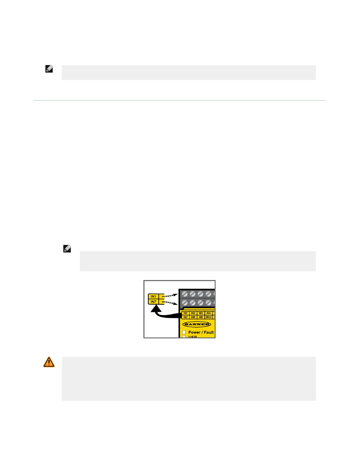
Figure 57. Input and output terminal locations
WARNING: Input Device and Safety Integrity
The Safety Controller can monitor many different safety input devices. The user must conduct a Risk
Assessment of the guarding application to determine what Safety Integrity Level needs to be reached in
order to know how to properly connect the input devices to the controller. The user must also take
steps to eliminate or minimize possible input signal faults/failures that may result in the loss of the
safety functions.
XS/SC26-2 Safety Controller
67