8 Operating Instructions
The Safety Controller can be operated using either the Onboard or PC Interface to monitor ongoing status.
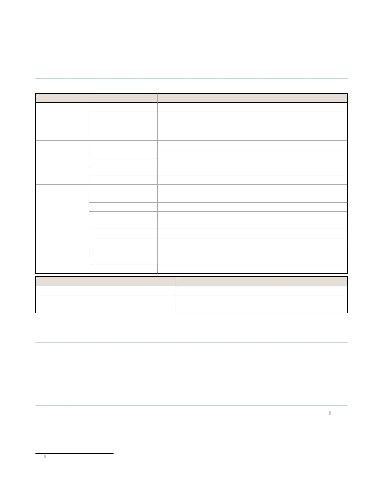
8.1 LED Status
LED Status Meaning
All
Off Initialization Mode
Sequence:
Green On for 0.5 s
Red On for 0.5 s
Off for 0.5 s min
Power applied
Power/Fault
Off Power Off
Green: Solid Run mode
Green: Flashing Configuration or Manual Power-Up mode
Red: Flashing Non-operating Lockout condition
Red: Fast Flashing Safety Bus Communication Issue
USB
(Base Controller)
Off No link to the PC established
Green: Solid Link to the PC established
Green: Flashing for 5 s XM configuration match
Red: Flashing for 5 s XM configuration mismatch
Inputs
Green: Solid No input faults
Red: Flashing One or more inputs is in the Lockout condition
SO1, SO2
Off Output not configured
Green: Solid Safety Output On
Red: Solid Safety Output Off
Red: Flashing Safety Output fault detected
LED Status for Split Outputs Meaning
Green: Solid Both outputs are On
Red: Solid SO1 and/or SO2 Off
Red: Flashing SO1 and/or SO2 fault detected
8.2 Live Mode Information - PC Interface
To display real-time Run mode information on a PC, the Controller must be connected to the computer via the SC-USB2
cable. Click Live Mode to access the Live Mode view. This feature continually updates and displays data, including Run,
Stop, and Fault states of all inputs and outputs, as well as the Fault Codes table. TheEquipment view and the Functional
View also provide device-specific visual representation of the data. See Live Mode on page 57 for more information.
The Live Mode view provides the same information that can be viewed on the Controller LCD (models with display only).
8.3 Live Mode Information - Onboard Interface
To display real-time Run mode information on the Controller LCD (models with display only), select System Status
8
from
the System Menu (see Onboard Interface on page 64 for navigation map). System Status shows input device and
Safety Output states; Fault Diagnostics shows current Fault information (a brief description, remedy step(s), and the
Fault Code) and provides access to the Fault Log.
The Controller display provides the same information that can be viewed via the Live Mode function in the PC Interface.
8
System Status is the first screen that displays when the Controller turns On after a reset. Hit ESC to view the System Menu.
XS/SC26-2 Safety Controller
103