Fault Exclusion
An important concept within the requirements of ISO 13849-1 is the probability of the occurrence of a failure, which can
be reduced using a technique termed "fault exclusion." The rationale assumes that the possibility of certain well-defined
failure(s) can be reduced via design, installation, or technical improbability to a point where the resulting fault(s) can be,
for the most part, disregarded—that is, "excluded" in the evaluation.
Fault exclusion is a tool a designer can use during the development of the safety-related part of the control system and the
risk assessment process. Fault exclusion allows the designer to design out the possibility of various failures and justify it
through the risk assessment process to meet the requirements of ISO 13849-1/-2.
6.3.2 Safety Input Device Properties
The Safety Controller is configured via the PC Interface to accommodate many types of safety input devices. See Adding
Inputs and Status Outputs on page 19 for more information on input device configuration.
Reset Logic: Manual or Automatic Reset
A manual reset may be required for safety input devices by using a Latch Reset Block or configuring a safety output for a
latch reset before the safety output(s) they control are permitted to turn back On. This is sometimes referred to as “latch”
mode because the safety output “latches” to the Off state until a reset is performed. If a safety input device is configured
for automatic reset or “trip” mode, the safety output(s) it controls will turn back On when the input device changes to the
Run state (provided that all other controlling inputs are also in the Run state).
Connecting the Input Devices
The Safety Controller needs to know what device signal lines are connected to which wiring terminals so that it can apply
the proper signal monitoring methods, Run and Stop conventions, and timing and fault rules. The terminals are assigned
automatically during the configuration process and can be changed manually using the PC Interface.
Signal Change-of-State Types
Two change-of-state (COS) types can be used when monitoring dual-channel safety input device signals: Simultaneous or
Concurrent.
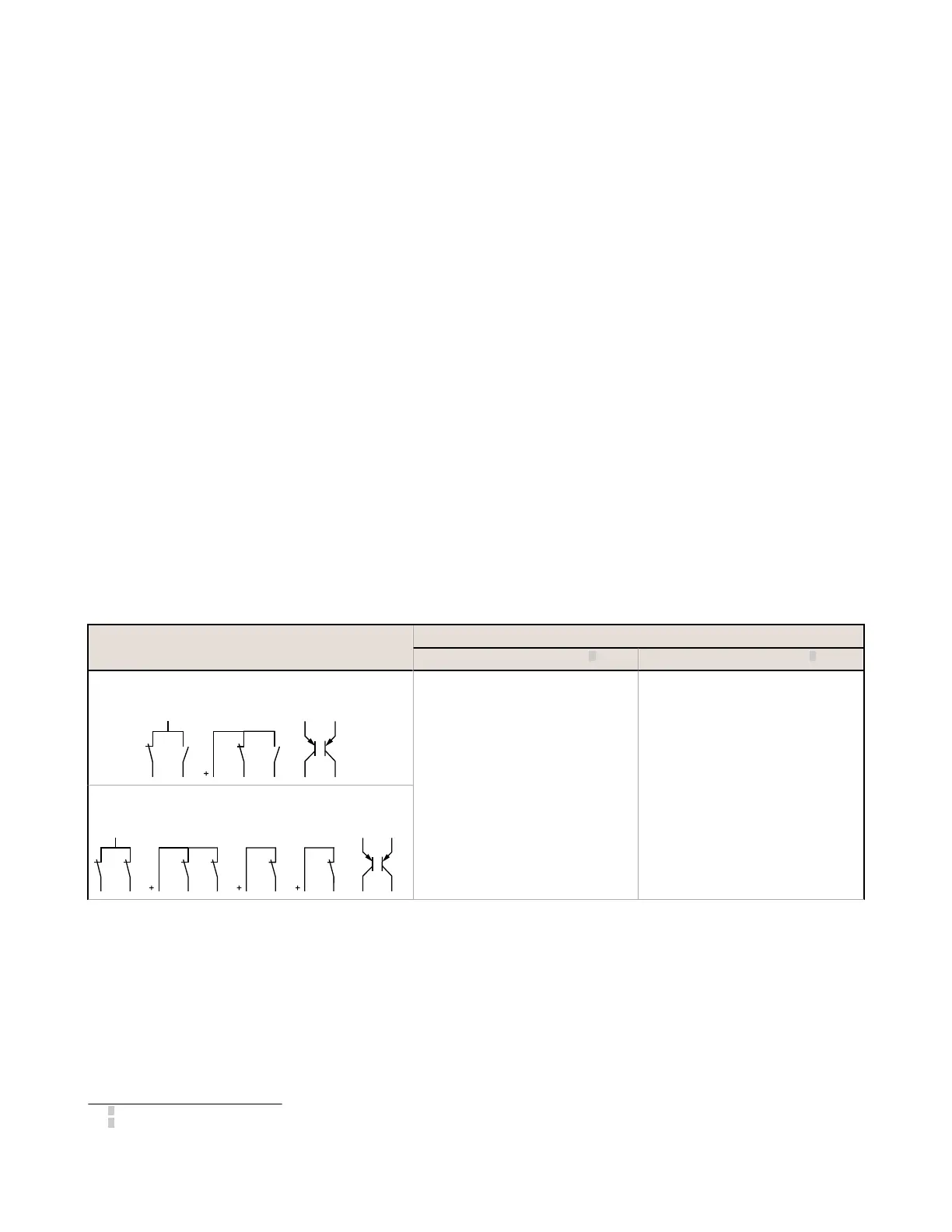
Input Circuit
Input Signal COS Timing Rules
Stop State—SO turns Off when
3
: Run State—SO turns On when
4
:
Dual-Channel A and B Complementary
2 Terminals 3 Terminals 2 Terminals, PNP
24V
OFFON
At least 1 channel (A or B) input is in the
Stop state.
Simultaneous: A and B are both in the
Stop state and then both in the Run state
within 3 seconds before outputs turn On.
Concurrent: A and B are concurrently in
the Stop state, then both in the Run state
with no simultaneity to turn outputs On.
Dual-Channel A and B
2-Ch, 2 Terminal
PNP
2-Ch, 2 Terminals 2-Ch, 3 Terminals 2-Ch, 4 Terminals
24V
ONON
3
Safety Outputs turn Off when one of the controlling inputs is in the Stop state.
4
Safety Outputs turn On only when all of the controlling inputs are in the Run state and after a manual reset is performed (if any safety inputs are
configured for Manual reset and were in their Stop state).
XS/SC26-2 Safety Controller
69

 Loading...


